General Tools and Instruments RLD400 User Manual
Page 6
IMPORTANT: The startup sequence will not execute to completion if the refrigerant gas
sensor cannot be heated. That would be the case if the sensor becomes electrically
disconnected from the probe.
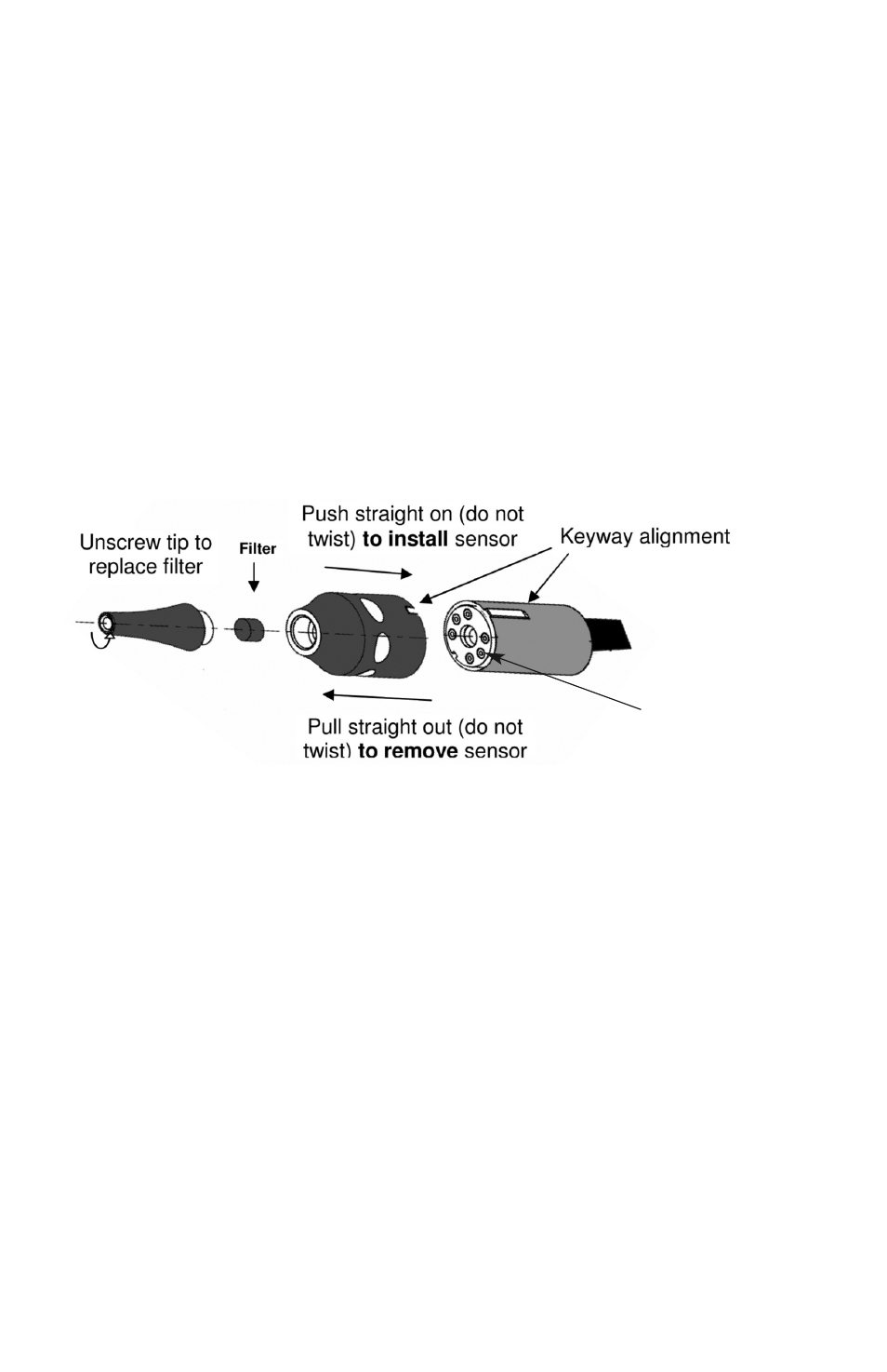
The sensor (which is under the black probe tip assembly) is physically and electrically
connected to the probe by a six-pin socket visible under the clear plastic near the red
“refrigerant detected” LED near the end of the probe (see figure below).
If the startup sequence fails to complete after 60 seconds, abort the process by
powering off the unit. Then check the integrity of the connection between the sensor and
the probe by doing the following:
1) Pull the black probe tip assembly straight out and away from the sensor socket
without twisting it. This disconnects the sensor.
2) Line up the keyway notch on the probe tip assembly with the raised keyway on the
sensor socket holder
3) Carefully push the sensor back into the socket without forcing or twisting it;
misalignment can damage the sensor’s pins. This reconnects the sensor.
CHECKING FOR LEAKS
Position the end of the RLD400’s flexible-obedient probe—which retains its configured
shape—close to any suspected source of leaking refrigerant gas. In a vehicle, wet oily
areas around hose connections and fittings, and greasy streaks radiating outward
around the compressor clutch or on the underside of the hood just above the
compressor are telltale signs of a leak. Another place to check sooner rather than later
is the evaporator (located inside the heater/defroster plenum under the dash).
Whenever the sensor at the end of the probe senses a refrigerant gas that it has been
designed to detect:
1) The red LED at the end of the probe will begin flashing much faster than three times
every two seconds
2) The beeper will increase its own frequency correspondingly
3) A number from 1 to 9 will appear in the digital leak size indicator window.
6
Sensor socket and
red “refrigerant
detected” LED