Product overview, Log button h. °f/°c, Fig. 1 fig. 2 – General Tools and Instruments IRT659K User Manual
Page 5
5
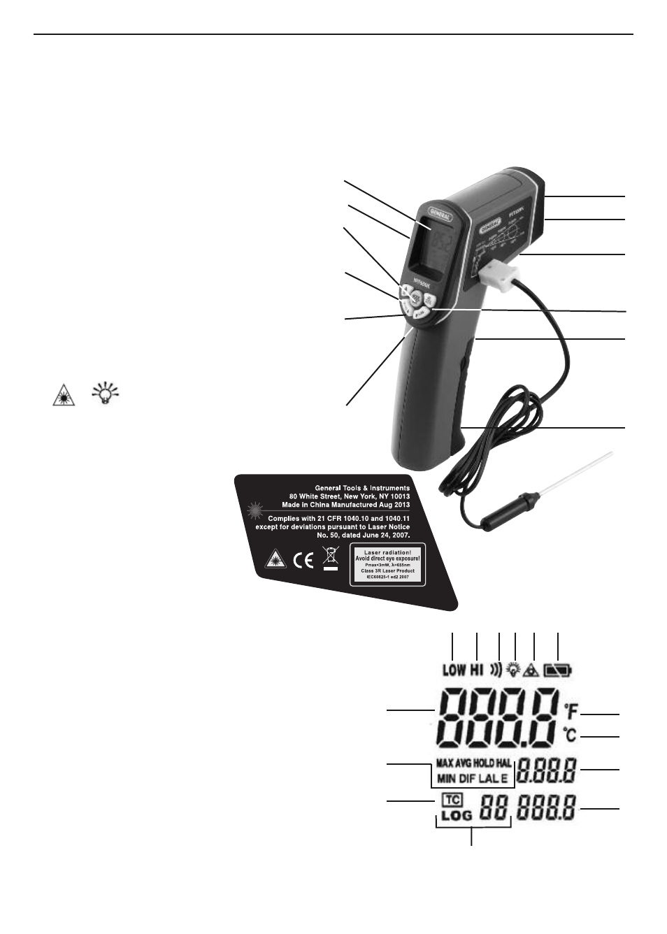
PRODUCT OVERVIEW
Fig. 1 shows all controls, indicators, connectors and other physical features of
the IRT659K. Fig. 2 shows all possible indications on the unit’s LCD. Familiarize
yourself with the positions of all controls and connectors and the meaning of all
display indications and icons before moving on to the Setup Instructions and
Operating Instructions.
A. Laser pointer B. Infrared sensor
C. Measurement trigger
D. Battery compartment
E. LCD F. MODE/SET button
G.
ĵ
LOG button
H. °F/°C
Ķ
button
I. IR/K (TC) button
J.
/
button
K. “K” type thermocouple probe
(shown inserted in socket)
L. Laser Identification/
Certification/Warning/
Safety Labels
(on left side)
A. Low temperature alarm
setpoint exceeded
B. High temperature alarm setpoint exceeded
C. Operating in scanning mode
D. Backlight on E. Laser pointer enabled
F. Low battery G. Main readout
H. Display mode indicators
I . “K” type thermocouple (TC)
measurement selected
J. Log # (01 to 10)
K. Log value L. Display mode value
M. Celsius unit N. Fahrenheit unit
A
E
L
F
J
H
G
B
K
I
C
D
Fig. 1
Fig. 2
A
B
C D E
F
N
M
L
K
G
H
I
J