Finish Thompson UC (S/N 125040 and lower) User Manual
Page 7
7
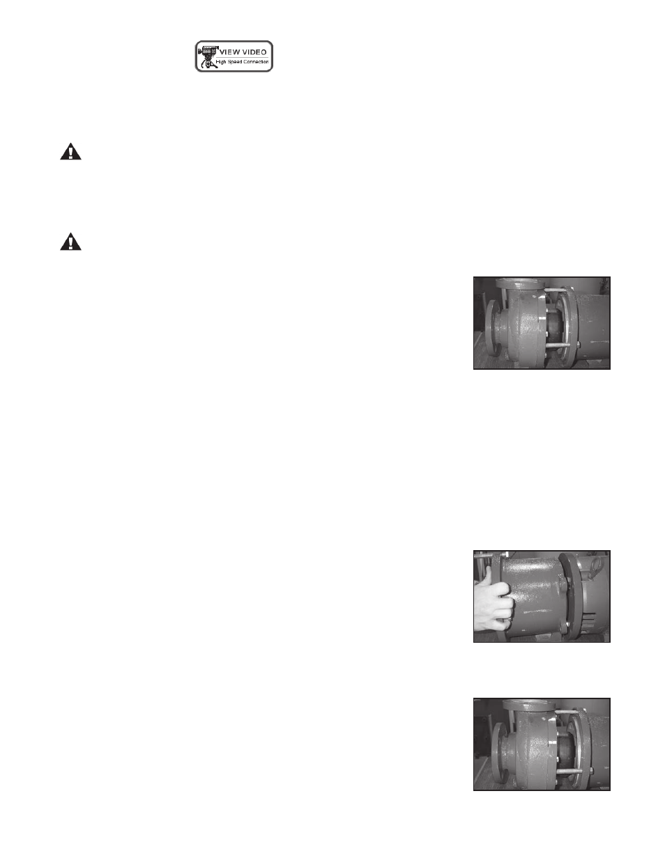
figure 3
Magnetic Force Hazard. This pump should only be disassembled and assembled
using the recommended procedures. The magnetic attraction is powerful enough to
rapidly pull the motor end and the wet end together. ALWAYS use the jackscrews (item
14) to assemble/disassemble the pump. Do not place fingers between the mating
surfaces of the motor and wet ends to avoid injuries. Keep the drive magnet and
impeller assembly away from metal chips or particles.
CAUTION: Keep the drive hub away from the open end of the motor adapter and
barrier. Strong magnetic attraction could allow the drive hub to enter the motor
adapter resulting in injury or damage.
3. Using a ¾” socket, unbolt the wet end (items 1-7) from the motor adapter by
removing the (4) ½” hex head cap screws (item 15). Extend the (3) jackscrews
(item 14). Using a ¾” socket turn the jackscrews clockwise. Turn the jackscrews
until they are fully extended. (See figure 1)
4. Place the motor adapter flange onto the motor face and securely attach with (4)
fasteners.
5. Coat the motor shaft with anti-seize paste. Slide the drive hub (item 8) onto
the motor shaft with the key in the keyway.
6. For installation onto 145TC, 184TC, 215TC and 256TC frames:
A. Slide outer drive onto motor shaft until end of shaft is firmly against retaining ring.
B. Using a “T” handled Allen wrench, tighten both setscrews to 228 in-lbs (25.8
N-m)
For installation onto 90, and 100/112 IEC motor frames:
A. Slide outer drive onto motor shaft until end of shaft is firm against retaining ring.
B. Install flat washer, lock washer, and bolt into the end of the motor shaft and then
tighten to the following torque settings:
90, 100/112 frame B14 - 14.7 N-M (130 in-lbs)
For installation onto 132 frame B5 motors:
A. Slide outer drive onto motor shaft until end of shaft is firmly against retaining ring.
B. Install bolt and retaining washer (tapered side out) and torque to 64.5 N-m
(47.6
ft-lbs).
For installation onto 160/B5 motor frames:
A. Slide drive onto motor shaft until it hits motor. Position drive retainer on the end of
the motor shaft and secure with flat washer, lock washer and bolt. Torque bolt to
160.3 N-m (118 ft-lbs).
B. Pull outer drive away from motor until it is firmly against drive retainer. Using a
3/16 “T” handled hex wrench, tighten setscrews to 22.8 N-m (228 in-lbs).
7. Slide the motor adapter (item 9) over the drive hub and attach it to the motor
flange. Install (4) supplied 3/8-inch hex head cap screws (item 16) and torque
evenly to 35 ft-lbs (47 N-m) (see figure 3 ).
8. Carefully slide the wet end towards the motor adapter until it touches the
jackscrews (there will be some magnetic attraction) (see figure 4) .
Pumps without Motors:
1. Prepare to install the motor on the pump. Carefully place the motor and pump end on a suitable, level work surface
(a nonmagnetic surface is preferred). Make sure the work surface is free of metal chips or particles.
2. Using a 9/16” open-end wrench, remove the (4) 3/8” hex head cap screws (item 16) from the motor adapter flange
(item 10) and motor adapter (item 9).
figure 4
figure 1