Finish Thompson UC (S/N 125040 and lower) User Manual
Page 12
12
1. Stop the pump, lock out the motor starter, close all the valves that are connected to the pump, and
drain/decontaminate the pump. The ULTRAChem is supplied with a casing drain to help drain and decontaminate
the pump. If the drain flange has been removed to drain/decontaminate the pump, reinstall the flange (item 11) and
use a new gasket (item 11A). Torque the two flange bolts (¼”) (item 11B) to 20 ft-lbs (27.1 N-m).
2. Allow the pump to reach ambient temperatures prior to performing
maintenance.
3. Remove the mounting bolts that attach the motor to the base, if any.
Using a ¾” socket, remove the (4) ½” bolts (item 15) that secure the
motor adapter (item 9) to the clamp ring (item 7) (see figure 8).
4. Separate the magnetic coupling between the drive end and the pump end by using the (3) jackscrews
(item 14). Using a ¾” socket turn the jackscrews clockwise. Be sure to turn the jackscrews evenly. Turn the
jackscrews until they are fully extended (see figure 9).
CAUTION: After removal of the drive end, the jackscrews should be
left fully engaged in the adapter to prevent accidental attraction of
the magnetic coupling.
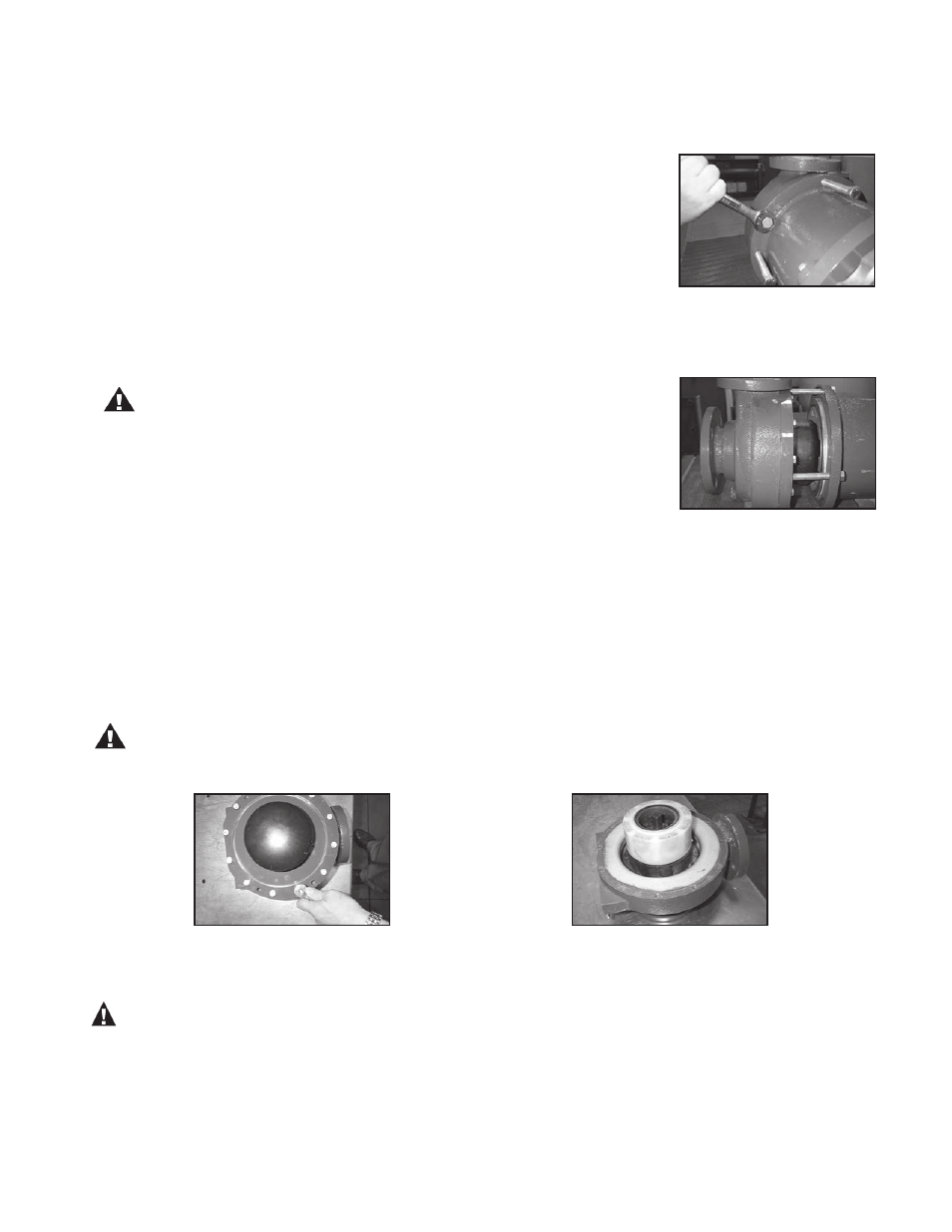
5. Using a 9/16” socket, remove the (12) 3/8” hex head bolts (item 13) that
connect the clamp ring to the casing (item 1). (See figure 10).
6. Remove the clamp ring from the back of the barrier assembly (item 6).
7. Place the casing/barrier assembly on a table with the suction flange of the casing facing down. Carefully re-
move the barrier assembly from the casing. It may be necessary to gently pry with a flat blade screwdriver between
the barrier assembly and the casing to help loosen the o-ring fit. When pulling the barrier assembly out of the cas-
ing, the shaft and the impeller will normally be left in the casing. Occasionally the shaft will stick in the barrier. If this
happens, make sure that the shaft does not drop out when the barrier assembly is removed or damage may result.
8. Remove the impeller assembly and the shaft from the casing (see figure 11).
CAUTION: The shaft and impeller can be damaged if dropped.
figure 8
figure 9
figure 10
figure 11
Power End (motor side)
WARNING: This pump should only be disassembled and assembled using the recommended procedures. The
magnetic attraction is powerful enough to rapidly pull the motor end and the wet end together. ALWAYS use the jack-
screws (item 14) to assemble/disassemble the pump. Do not place fingers between the mating surfaces of the motor
and wet ends to avoid injuries. Keep the drive magnet and impeller assembly away from metal chips or particles.