Finish Thompson MSKC series User Manual
Page 3
3
BUSHiNG rePLACeMeNT
1. To remove the bushing in the second stage, insert 1/16” pin
punch into balance hole (inner circle of 4 holes) of impeller
drive. Gently tap the bushing out of the back of the impeller
drive. The punch may need to be moved to a different hole if
the bushing is difficult to remove.
2. To replace the bushing, clean the impeller bore. insert the new
bushing into the back of the impeller drive by aligning the
bushing with the impeller bore. Press gently until the bushing
bottoms out (use a block of wood and mallet if necessary).
3. if the bushing in the impeller drive shaft is worn and needs
to be replaced, the complete impeller drive shaft with bush-
ing (item 3) will need to be purchased. Grasp the impeller
assembly in one hand and pull the impeller drive shaft from it.
reASSeMBLY
if the drive magnet assembly (item 10) is to be replaced, install as
follows. On a 56C motor frame, slide the drive magnet assembly
(item 10) onto the motor shaft until it is between 3.110” and
3.120” as measured from the motor face to the top of the magnet
assembly. See figure 1. Align cone point set screw (item 10B)
with key slot on the motor shaft and tighten both set screws with
a 5/32” Allen wrench to 140 in-lbs. (15.8 N-m).
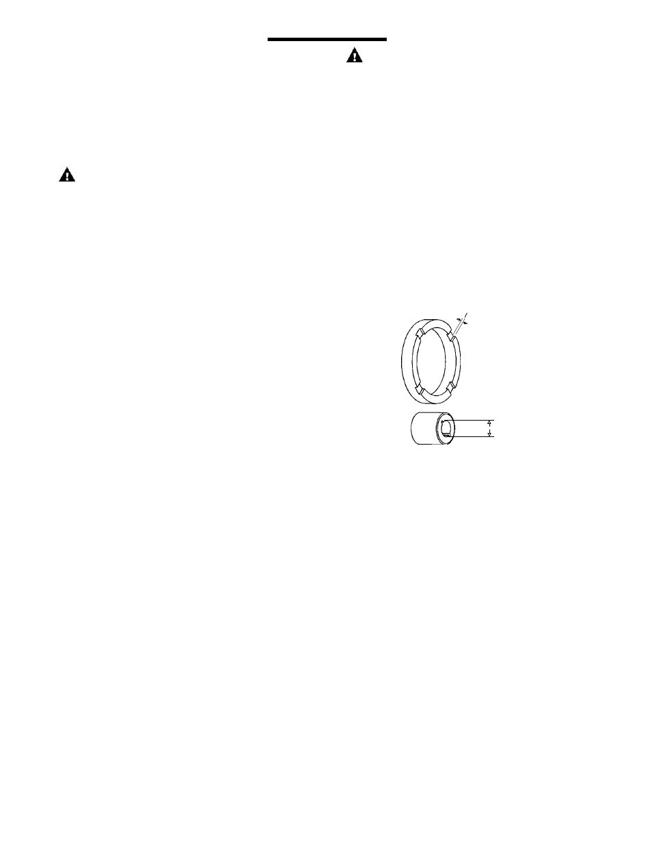
.020” min.
.415” max.
Figure 5
SUCTiON LiFT SYSTeM
1. Prime the system by filling the priming chamber and/or suc-
tion line with a liquid. Allow time for trapped air to work its
way out.
2. if priming via filling the suction line, close the discharge valve
prior to returning the suction line to the tank.
MAiNTeNANCe
DiSASSeMBLY
1. Disconnect power. remove electrical wiring and motor
mounting bolts.
2. Close suction and discharge valves. Disconnect piping.
3. Securely hold or clamp motor in place.
4. For 71/80 motor frame pump, skip to step 5. For 56C motor
frame pumps, remove the four motor adapter bolts (item 14A)
and pull the pump end away from the motor/drive magnet
assembly. Set pump end on motor adapter flange with suc-
tion facing up.
5. remove the six screws (item 12A) from the impeller housing.
6. Using a thin bladed screwdriver, gently separate the first
stage housing (item 1) from the diffuser (item 5). remove
the first stage impeller housing (item 1) being careful to pull
straight off so as not to damage the ceramic front spindle
support. remove the housing o-ring (item 4). Holding down
on the outside of the diffuser assembly (item 5) with one
hand, gently pull the first stage impeller/impeller drive shaft
assembly (items 2 and 3) from the pump.
7. remove the diffuser assembly (item 5) and the diffuser o-ring
(item 6) from the top of the second stage impeller housing
(item 7). remove the second stage impeller housing, the
housing o-ring, the second stage impeller assembly (items
2 & 8), and the barrier (item 9) from the motor adapter (item
11).
8. if the drive magnet assembly (item 10) or the motor needs to
be replaced, do the following. On 56C frame motors, loosen
the two drive magnet set screws (items 10A and 10B) with a
5/32” hex wrench, and remove the drive magnet assembly.
On 71/80 frame motors, insert a 5/32” hex wrench into the
access hole on the top of the motor adapter (item 11) and
loosen the two set screws. remove the drive magnet as-
sembly from the motor shaft. remove the motor adapter if
the motor is being replaced.
FLUSH SYSTeMS
Caution: Some liquids react with water.
1. Completely close suction and discharge valves.
2. Connect water supply to water inlet valve.
3. Connect drain hose to water valve.
4. Open inlet and outlet valves. Flush system until pump is clean
(approximately 5 minutes).
Caution:
Keep the drive magnet and impeller assemblies away from
metal chips or particles.
exAMiNATiON
1. Check impeller bushings (item 8A) in both the impeller as-
sembly (item 8) and the impeller drive shaft (item 3), check
both thrust rings (item 2A), both ceramic housing rings, and
both the barrier ceramic post and the first stage impeller
housing ceramic post for cracks, chips, scoring or excess
wear. See figure 5. replace as required.
2. Check for loose magnets on drive magnet assembly or rubbed
areas on the impeller or barrier assemblies. Contact your
distributor or FTi Technical Service if a problem is found.
3. if you do not remove the drive magnet assembly, check the
set screws for tightness before reassembly.