Finish Thompson MSKC series User Manual
Page 2
2
5. Place wet end assembly (comprised of items 1-9) into the
motor adapter (item 11). Grasping the barrier at opposite
bolt tabs, carefully lower the wet end assembly into the mo-
tor adapter/drive assembly. Line up the tabs of the wet end
between the tabs on the motor adapter to avoid pinching
fingers. Once seated, rotate the wet end until bolt holes line
up.
6. Align mounting holes and install 6 mounting screws and
washers (items 12A, 12B & 12C) from hardware package.
Hand tighten screws using pattern shown in Figure 3.
7. rotate motor fan to verify there is no internal binding or rub-
bing.
8. install pump into the system according to installation instruc-
tions.
iNSTALLATiON
MOUNTiNG
Motor should be securely fastened.
PiPiNG
1. Support piping near the pump to eliminate any strain on the
pump casings.
2. Do not overtighten the piping on the discharge on initial
installation. Damage to the discharge can occur. An o-ring
can be used when there is wear and the plastic threads are
loose.
Note: BSP housings are shipped with an o-ring on the dis-
charge.
3. To minimize head loss from friction:
a. increase pipe size by 1 diameter.
b. Use minimal number of pipe bends.
4. Keep bends and valves a minimum of 10 pipe diameters from
the suction and discharge.
5. Position pump as close to the liquid source as possible.
6. Maintain a flooded suction (liquid above pump prior to being
primed).
7. ensure that the piping does not leak and suction is not prone
to clogging.
8. if flexible hose is preferred, use a reinforced hose rated for the
proper temperature and pressure. This helps avoid collapse
or kinks.
eLeCTriCAL
install motor according to NeC requirements and local electrical
codes. Motor should have an overload protection circuit.
iMPoRtant: To verify correct motor rotation:
1. install pump into system.
2. Fully open suction and discharge valves.
3. Allow fluid to flow into the pump. Do not allow pump to run
dry (PTFe and ceramic bushings cannot be run dry without
damage to pump components).
4. Jog motor (allow it to run for one or two seconds) and observe
rotation of motor fan. Correct rotation is clockwise as viewed
from motor fan. refer to directional arrow on pump.
note: A pump running backwards will pump but at a greatly
reduced flow and pressure.
OPerATiON
FLOODeD SUCTiON SYSTeM
1. Completely open suction and discharge valves
2. Start the pump and check liquid flow. if there is no flow, see
the Troubleshooting section.
3. Adjust the flow rate and pressure by regulating the discharge
valve. Do not attempt to adjust the flow with the suction valve.
6
1
2
3
4
5
Figure 3
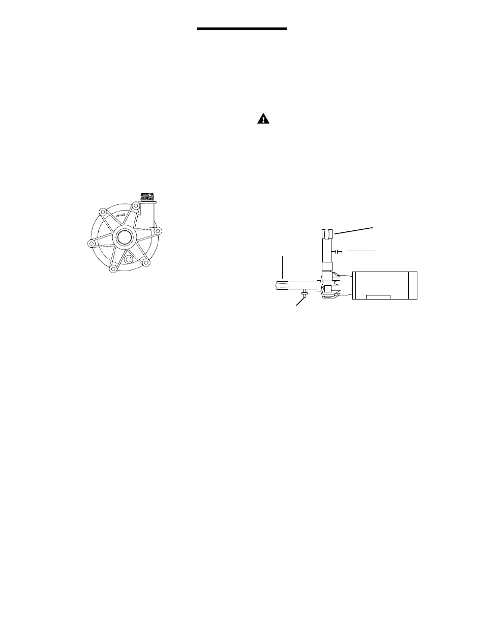
Suction
Valve
Water
Outlet
Valve
Discharge Valve
Water Inlet Valve
Figure 4
9. install valves on suction and discharge lines (a minimum of
10 pipe diameters from the pump).
10. For units in a suction lift system, install appropriate piping in
the discharge to allow priming of the pump.
note: This pump is not self-priming.
11. The suction valve should be completely open to avoid
restricting suction flow.
Caution:
To stop the pump if prime is lost, use one of the following:
(1) pressure switch on the discharge, (2) vacuum switch on
the suction, (3) a power monitor to monitor motor power.
12. When pumping liquids that may solidify or crystallize, a flush
system should be added to the piping. See Figure 4. install
water inlet and outlet valves as shown.
note: This pump is provided with a provision for a customer
installed 1/4” NPT drain in the impeller housing. See Drain
installation Section for details.