Sp22 assembly, installation and operation – Finish Thompson SP22 Series Self-Priming User Manual
Page 6
6
SP22 Assembly, Installation and Operation
Unpacking and Inspection
Unpack the pump and examine for any signs of shipping damage
If damage is detected, save the packaging and notify the carrier
immediately
Section I - Assembly
Tools Required:
3/8” Allen wrench or ballpoint hex socket, 3/16” Allen wrench,
10 mm hex socket, metric socket set (for pumps with IEC outer
drives)
Pumps with Motors
Proceed to “Installation” Section
Pumps Without Motors
NOTE: All motors must have motor feet
1 Remove the pump, drive magnet assembly and hardware
package from the carton
CAUTION: Keep away from metallic particles, tools and
electronics Drive magnets MUST be free of metal chips
WARNING: Keep the drive magnet away from the open end
of the motor adapter and barrier Strong magnetic attraction
could allow the drive hub to enter the motor adapter result-
ing in injury or damage
2. For 184TC motors, proceed to step 3
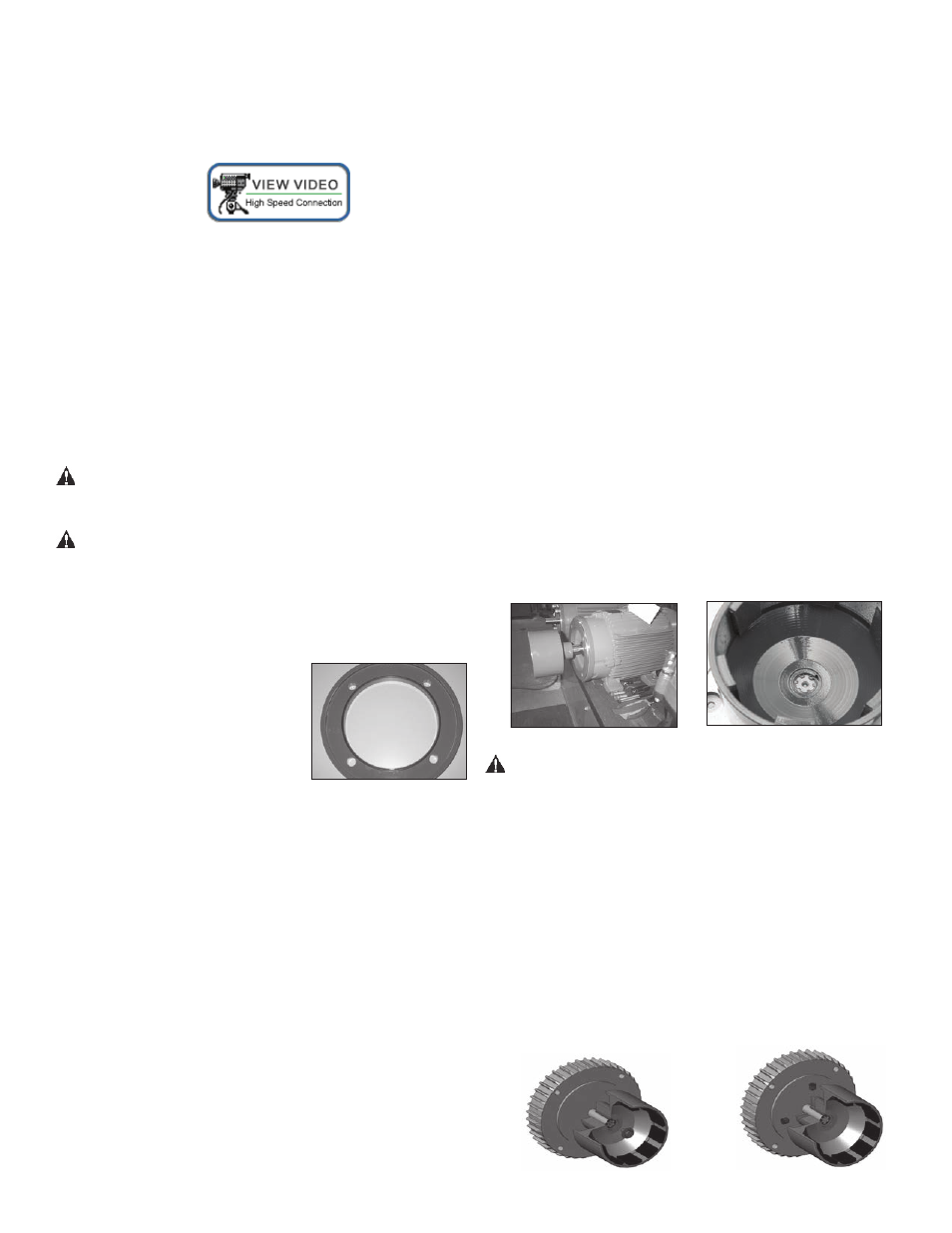
For 213/215 NEMA motors only
– Install the o-ring (item 14A) in
the groove in the motor adapter
Use small amount of petroleum
jelly (or silicone grease on EPDM
o-rings) to help hold the o-ring in
place Install the larger female
rabbet portion of the motor adapter flange (item 14) on the
motor face Align the holes in the adapter with the holes in
the motor face See figure 1
For IEC 90, 100/112, 132 with B5 flange motors - Install
flange (item 14) on motor with pockets (depressions) side
towards the motor face Align (4) holes in the adapter with
the holes in the motor face install the (4) customer supplied
bolts, lock washers and flat washers through the motor
adapter into the motor face See figure 1
Flange hole thread size:
90 B5 = M10 x 1 5
100/112 B5 = M12 x 1 75
132 B5 = M12 x 1 75
For 90 & 132 with B14 flange & 145TC motors - Install
the flange item 14) on motor with pockets (depressions) side
towards the motor face Align (4) holes in the adapter with
the holes in the motor face Install (4) bolts, lock washers
and flat washers (items 24, 25, 26) through the motor
adapter into the motor face See figure 1
For 100/112 with B14 flange motors
Install flange (item 10) on motor with pockets (depressions)
towards the pump motor adapter (item 8) Align (4) holes in
the adapter with the holes in the motor face Install (4) bolts,
lock washers and flat washers (items 20, 21, 22) through
the motor adapter into the motor face
Torque bolts to the following:
90/100/112 B14 frame (M8) = 130 in-lb (14 7 N-m)
132 B14 (M10) frame (M10) = 240 in-lb (27 1 N-m)
90 frame B5 (M10) = 240 in-lb (27 1 N-m)
100/112/132 B5 (M12) = 480 in-lb (54 3 N-m)
3 Coat the motor shaft with anti-seize compound Insert key
supplied with motor into keyway on motor shaft
NOTE: Make sure the motor shaft is clean and free of burrs
The outer drive is precision machined and has a bore toler-
ance of + 0005/-0 inch
4 Slide the outer drive magnet assembly (item 13) onto the
motor shaft until the motor shaft contacts the snap ring in
the bore of the drive Figures 2 and 3
Figure 2
Figure 3
WARNING: Be careful, magnets will try to attract tools
Metric Motors: Secure the drive to the motor shaft using
bolt, lock washer and flat washer (items 21, 22, 23) Thread
the bolt into the end of the motor shaft (while holding the
outer drive to prevent it from turning) See figure 4
Tighten the bolt to the following:
· 90 frame (M8)
= 130 in-lb (14 7 N-m)
· 100/112 frame (M10) = 240 in-lb (27 1 N-m)
· 132 frame (M12) = 480 in-lb (54 3 N-m)
NEMA Motors: Install set screws (item 13B) into threaded
holes on the side of the outer drive magnet assembly Using
a 3/16” Allen wrench, tighten to 228 in-lbs (25 8 N-m) See
figure 5
Figure 4
Figure 5
Figure 1