Finish Thompson SP22 Series Self-Priming User Manual
Page 10
10
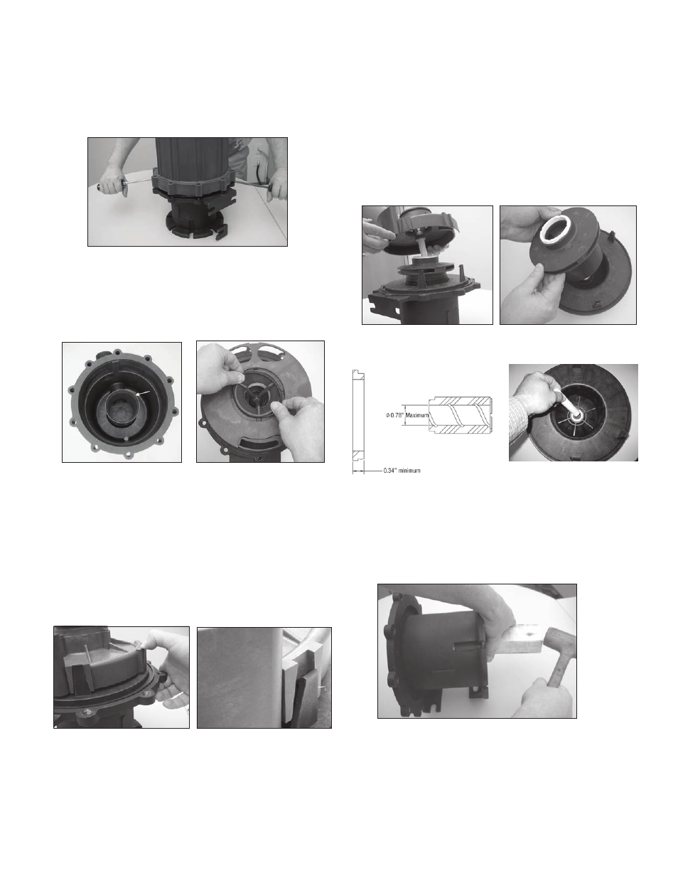
Applying equal pressure, gently pry both screwdrivers in
upward motion away from the table (to avoid damaging
sealing surface) See figure 12A Housing is tight due to o-
ring seal on the internal “gooseneck”
NOTE: Do not twist the screwdrivers or damage may occur
to the housing
5 Examine the housing for signs of wear or damage Inspect
the gooseneck and suction and discharge for cracks See
figure 13 Inspect fill and drain plug o-rings (item 2A) for
chemical attack, swelling, brittleness, cuts, etc
Figure 12A
Figure 13
6 Carefully remove the inner volute o-ring (item 4) See figure
14 Inspect for chemical attack, swelling, brittleness, cuts, etc
7 Pull the separator plate (item 5) off the inner volute (item 6)
Inspect for damage and cracks
8 To remove the inner volute (item 6), pull back on the (3) snap
fit prongs one at a time so that the hook portion falls into the
channel on the inner volute See figures 15 and 16
Figure 14
Figure 15
Figure 16
9 Pull the inner volute straight off Be careful since the impeller
shaft may come out with the inner volute See figure 17
10 Remove impeller/inner drive assembly (items 7A, 7, 8, 8A)
Inspect for signs of rubbing, damage and wear See figure
18 Check the impeller thrust ring and bushing for wear See
figure 19
11 Remove the impeller shaft (item 9) from the barrier and
check for signs of cracking, chipping, scoring or wear See
figure 20
Figure 17
Figure 18
Figure 19
Figure 20
12 Remove the barrier (item 11) from the motor adapter (item
12) (make sure the impeller shaft has been removed) If nec-
essary, gently tap on the backside of the barrier with a soft
rod (wood, plastic, etc) Inspect the inside and outside of the
barrier for signs of rubbing See figure 21
Figure 21