Farm Star T55-74 User Manual
Page 26
25
18
I N S T R U C T I O N S
(continued)
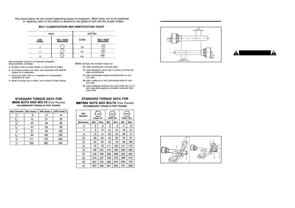
P R O P E R T O R Q U E F O R FA S T E N E R S
A S S E M B LY
(continued)
1. Place the two halves of the driveline together, keeping
them parallel (see Figure 3). Using a felt-tip pen,
matchmark the place where the two halves must be
shortened, measuring 1.0 inch from the beginning of
each half, as shown in Figure 3.
Double check before making any cuts. Cut PTO
drivelines cannot be returned.
Figure 3
Figure 4
2. Raise and lower the mower to determine position with
greatest distance between the PTO shaft and gearbox
input shaft. Shut tractor off, leaving tiller in position of
greatest distance between shafts. SECURELY
BLOCK TILLER IN POSITION.
3. Hold driveline sections parallel to each other and
check for minimum 6” (15cm) overlap. If driveline
has been marked for cutting, overlap will be the
distance between the two marks. If driveline has less
than minimum overlap, do not use. Contact
authorized Worksaver dealer.
5. Repeat the procedure to the other driveline half.
Remove all burrs and cuttings.
6. Apply multi-purpose grease to inside of outer (female)
driveline section. Assemble driveline and install on
tractor and tiller. Pull on each driveline section to be
sure yokes lock into place. Make certain driveline
shielding is in place and in good condition.
4. If driveline must be cut to a shorter length, clamp
driveline in a well padded vise to prevent damage to
the shield. Cut off shield where marked. Using cut-off
section of shield as a guide, cut shaft the same
amount. (Figure 4.)
W A R N I N G !
When attaching PTO yoke to tractor PTO shaft, it is
important that spring-activated locking pin or balls
operate freely and are seated in groove on PTO shaft.
A loose shaft could slip off and result in personal
injury or damage to equipment.
If the PTO driveline assembly contacts the swinging
drawbar, damage will occur to the driveshaft shield and
possibly the driveshaft itself. (NOT covered under
warranty.)
8. Check the swinging drawbar of the tractor and make
sure the PTO driveline assembly will not contact. The
swinging drawbar can be moved forward on some
tractors or it can be removed.
Use the lift control limiting stop on the tractor control
lever to limit the upward travel of the lever so the lift can-
not be raised high enough to cause contact between the
drive shaft shield and front shielding. It is recommended
that the tiller not be raised more than 14 inches off the
ground with the PTO engaged.
NOTE: This type of damage is NOT covered under
warranty, as it is totally under the control and the
responsibility of the operator.
Then raise the tractor lift very slowly, making sure that
the front drive shaft shield does not hit the front of the
tiller. If it does, damage will be done to the drive shaft
shield and, if interference is bad enough, it WILL also
damage the drive shaft itself.
7. Carefully raise and lower the tiller and check to be sure
the PTO assembly does not jam. If it does, cut equal
amounts from each half of the PTO assembly.