Fairbanks Trident Precast Concrete Deck Truck Scale User Manual
Page 23
Section 3: Scale Installation
04/11
23
51255 Rev. 2
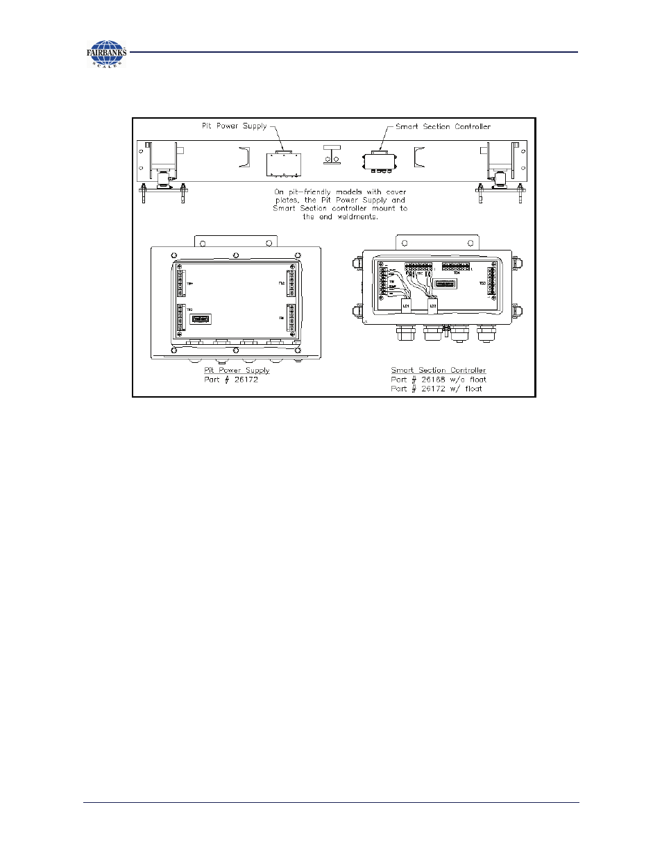
Cover plate model:
NOTE: All Tridents come standard with Intalogix. If the analog model is ordered
(Box 21912) mount as follows:
Balance box 21912 – Installation for analog instruments
1. Introduction – Balance box 21912 is to be installed at the platform, one box per section.
2. Description – Each stainless steel balance box has four (4) terminal blocks to
connect two (2) load cells and two (2) cables for connection to the analog
instrument. Load cells and sections are adjusted using adjusting potentiometers.
3. Installation –
a. Boxes: The box has tabs for bolting to mounting brackets on the side of
the modules. (See figure 51255-10.) or if cover plated, under each
sectional cover plate (See figure 51255-11.) Attach the ground wire lug to
one of the mounting bolt studs and tighten securely to provide a good
electrical ground.
b. Wiring: Cable used in all wiring must be a minimum of 18 AWG. Use
cable 17204 or equivalent. The balance boxes are interconnected from
TB1 to TB2 or TB2 to TB2 beginning at the end section where the interface
cable conduit enters the scale. An alternate method, if the conduit enters
the scale in the middle, is to use 14478 instrument SVP. This will allow
separate connections to go in each direction toward the ends of the scale.
See bulletin 50513 for the wiring diagrams.
51255-11
Cover plated model