Fairbanks 6020 Titan Series User Manual
Page 11
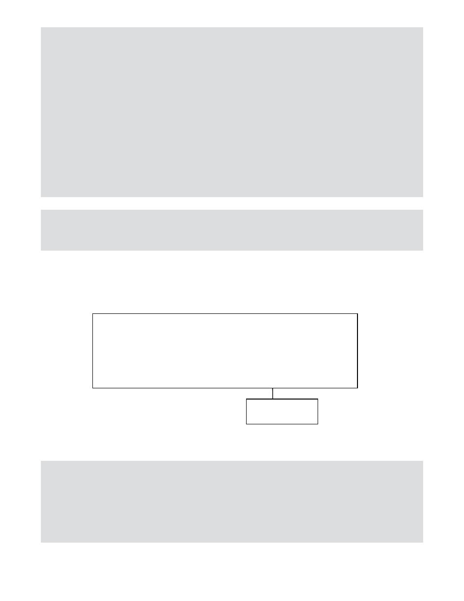
Example of three (3) section cell numbering:
Intalogix
™
System Inst
1
3
5
2
4
6
50598-2
Notes: The Titan PV scale has been designed to provide protection from the effects of
moisture. The load cells have been calibrated with the cable attached, therefore the
cable should NOT be cut.
The cable is connected directly to the sectional controller through a sealed gland
fitting which MUST be tightened properly to keep water/moisture out of the box.
All cabling should have a drip loop at the cell or box entry location to help prevent
water entry.
On all boxes, the load cell cable gland fittings have O-rings that can be forced out of
position if tightened improperly. To prevent this, first tighten the inner nut securing
the gland in the hole, insert the cable, and carefully tighten the gland. Do not over-
tighten where the gland turns. The cover MUST be secured with ALL screws
tightened properly (10 in/lbs.) for protection against moisture.
Note:
Smart Sectional Controllers have connections for two (2) load cells, TB1 and TB2. The odd
numbered cell connects to TB1 and the even numbered cell connects to TB2.
Note:
Intalogix™ installations utilize a specific numbering system for load cells because of digital
addressing of the SSCs. Number the load cells as follows: With respect to the following
starting position, face the platform from where the indicator is located. The cell at the upper
left or far side of the platform is Cell 1. The cell positions along the far side will be odd cell
numbers, the near side locations will be even cell numbers.
50753
11
12/12
-- Issue 5