Step 18b main gas valve coil check – A.O. Smith 120 trough 500 User Manual
Page 42
BTR TANK TYPE HEATERS
SERVICE HANDBOOK
A.O. Smith Water Products
Service Handbook
Irving, Texas ©2000
Training Department
41
STEP 18B
MAIN GAS VALVE COIL CHECK
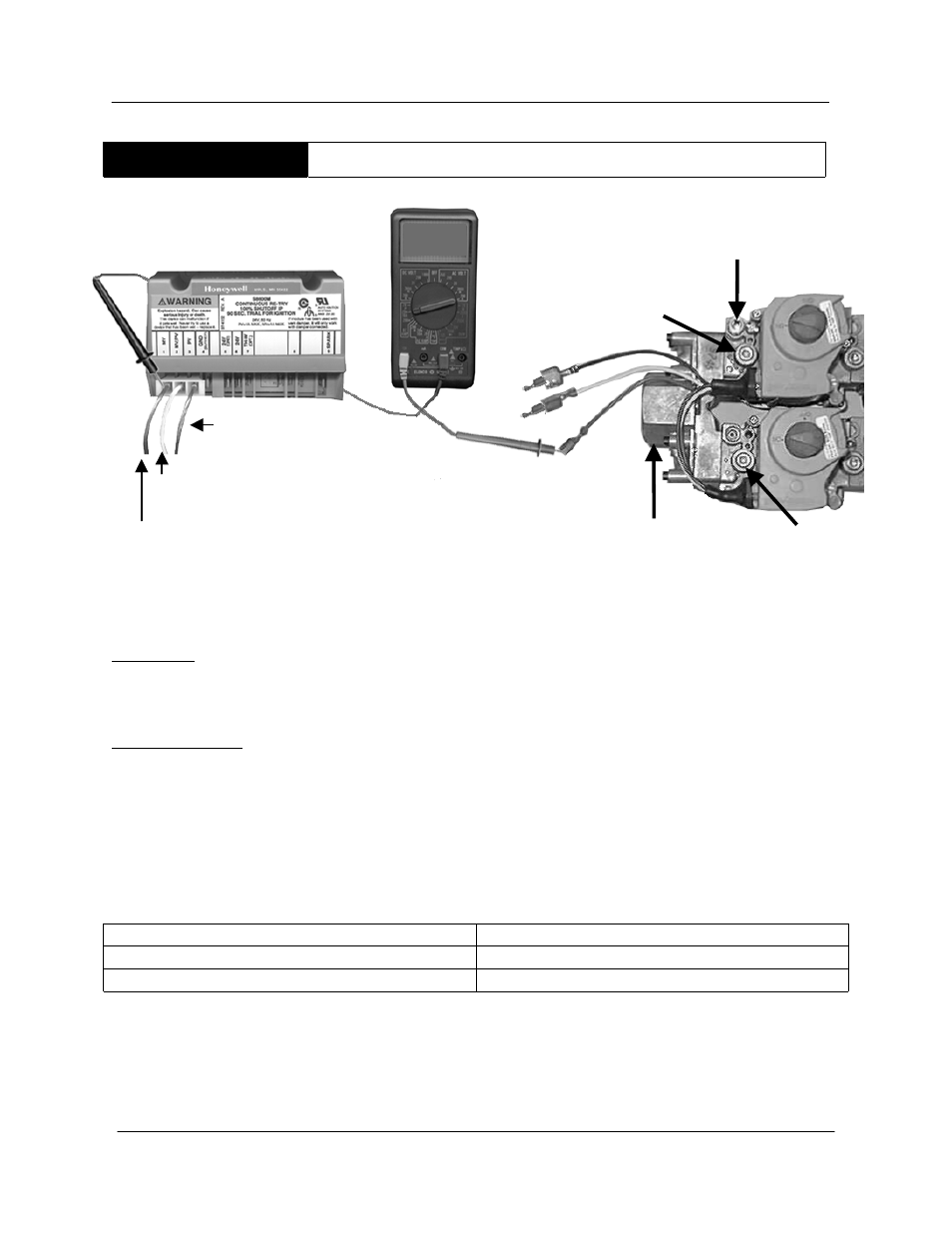
STEP 18B. MAIN GAS VALVE COIL CHECK – BTR 500 ONLY
Condition:
•
Pilot lights
•
Sparking stops
•
No main burner ignition
Test Procedure:
•
Power off
•
Disconnect red, main valve wire from module MV terminal
•
Meter set to test for DC amperage
•
10A wire to red gas valve wire, COM wire to MV terminal of ignition module
•
Turn power on to heater
•
After pilot lights and sparking stops
IF:
THEN:
.25 to .35 DC Amps is not present
• Replace the gas valve
.25 to .35DCA is present
• Main burner gas should ignite.
Be certain to correct you meter wire connections and setting before performing further
tests.
RED
WHITE
BLUE
MANIFOLD
PRESSURE
TAP
MANIFOLD
PRESSURE
TAP
PILOT GAS
MANIFOLD
GAS
The PV wire is connected to the blue wire
The MV/PV wire on the IID is connected to the white wire.
The MV wire is disconnected from the gas valve.