A.O. Smith 120 trough 500 User Manual
Page 27
BTR TANK TYPE HEATERS
SERVICE HANDBOOK
A.O. Smith Water Products
Service Handbook
Irving, Texas ©2000
Training Department
26
STEP 10
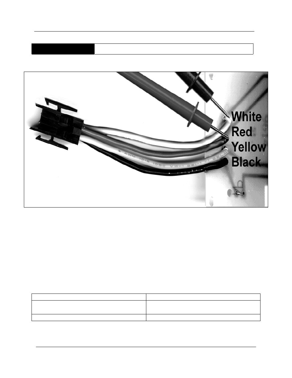
TEST DAMPER OUTPUT
STEP 10. TEST DAMPER OUTPUT.
On a call for heat, the damper relays receives
power through the yellow wire and power to the motor is interrupted.
Then, the motor
clutch is disengaged and the damper opens. The damper proves it is open via an end
switch before power flows through the red wire from the PC board.
Place the red test probe on the solder joint of the red wire connection to the damper PC
board.
IF
THEN
The meter does not read 24 VAC and the
end switch is closed:
• Replace the PC board
The meter reads 24 VAC
• Go to step 11.
Note: The spring rotates the damper blade assembly to the open position. This closes an end
switch.
- ACGSS02407 (4 pages)
- 401 (48 pages)
- 6-119 (28 pages)
- 1850 (36 pages)
- ADMP - 60 (6 pages)
- 750 (24 pages)
- 505 (2 pages)
- BTX-100 (2 pages)
- GW/GWO-2500 (4 pages)
- NW 37-670 (12 pages)
- BTP(V)-740A (6 pages)
- Genesis GB-1500 (2 pages)
- VWT-1000 (4 pages)
- AOSTT35300 (4 pages)
- 1300 (12 pages)
- BTP-199 (4 pages)
- ADM - 135 (74 pages)
- 1000 (80 pages)
- BTH-500A (8 pages)
- BTH 300A (36 pages)
- BTH 400A (36 pages)
- DB-720 thru 1810 (4 pages)
- BTP-378A (2 pages)
- BTI 120 (32 pages)
- AOSRG45300 (2 pages)
- AOSRG46600 (2 pages)
- VB/VW- 750 (52 pages)
- 300A (40 pages)
- 185363-001 (32 pages)
- AOSRE50400 (2 pages)
- TC-099 (74 pages)
- 25 litres (11 pages)
- ATI-705N (2 pages)
- XGV-50 200/201 (2 pages)
- 12 50GPC T 100 (56 pages)
- GB/GW-200 (10 pages)
- GWT-2500 (4 pages)
- VB 750 (8 pages)
- BTH 400 (1 page)
- 000 (4 pages)
- LB/LW: 500 (12 pages)
- VW-500 through VW-1000 (4 pages)
- BT-100 (2 pages)
- BTI-80 (2 pages)
- Voltex Hybrid Electric PHPT-80 (20 pages)