Btr gas valve – A.O. Smith 120 trough 500 User Manual
Page 13
BTR TANK TYPE HEATERS
SERVICE HANDBOOK
A.O. Smith Water Products
Service Handbook
Irving, Texas ©2000
Training Department
12
BTR GAS VALVE
The gas valves used on all BTR water heaters are
24 volt AC combination step opening gas valves.
They incorporate the pilot valve, main valve, and gas
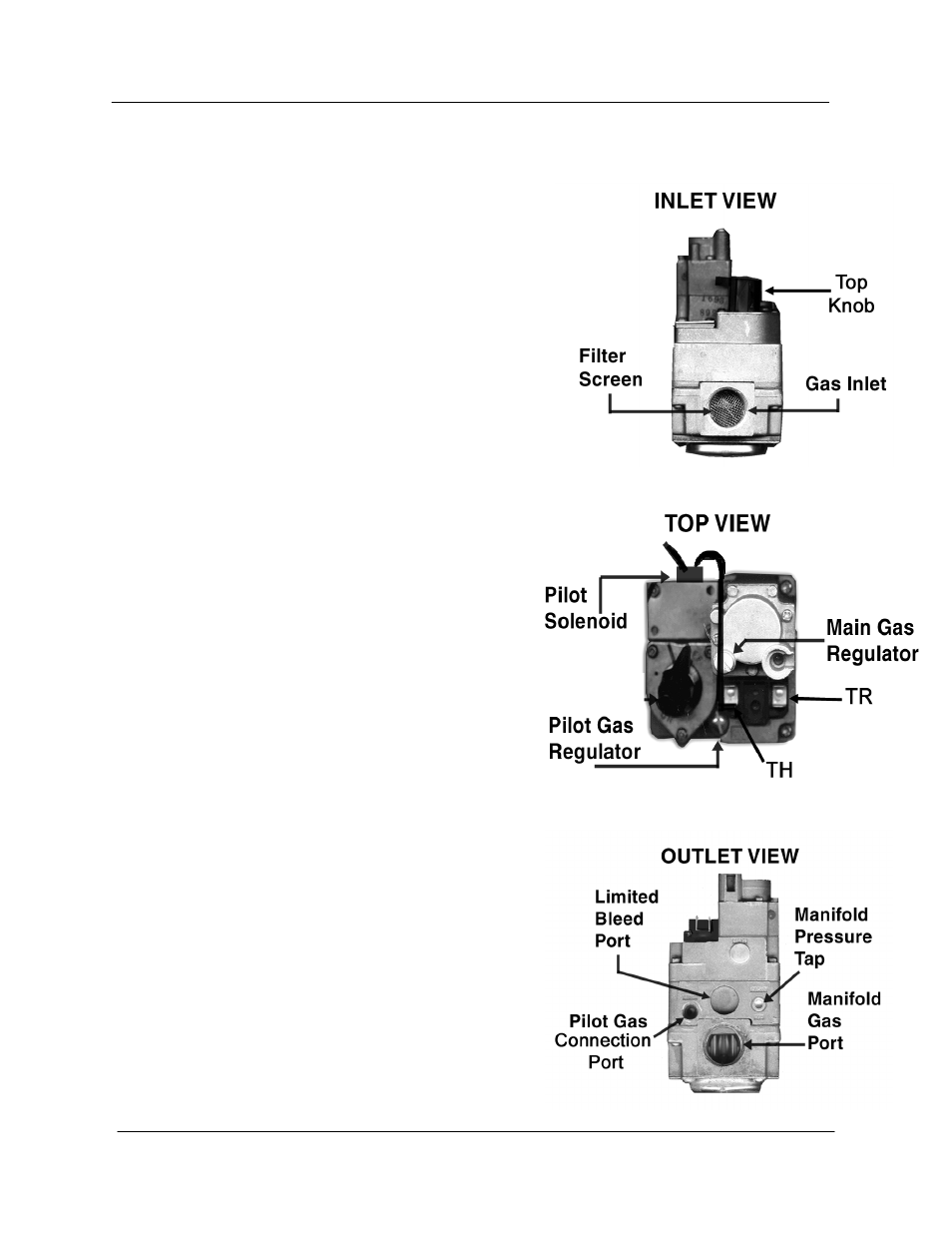
pressure regulators into one body. The inlet view of
the valve features a filter screen and the top knob.
The top knob is a manual on/off gas control for both
the pilot and main gas valves. When the top knob is
placed on the black mark, gas is supplied only to the
pilot valve.
On the top view, we see the pilot solenoid and
pilot and main gas regulators. The top view also
displays the “TH and “TR” terminals. The pilot
gas regulator is found under its cover screw. It is
factory preset at 3.5”w.c. but can be adjusted from
2.5 to 5 inches water column. The main gas
regulator is found under its cover screw. It is
factory preset to 3.5 inches w.c. and adjusts gas
pressure output from 2.5 to 5 inches water
column. The two electrical terminals are marked
TH and TR. The TH terminal is the common
between the pilot valve solenoid coil and the main
valve solenoid coil. The other wire emerging from
the pilot solenoid connects to the pilot valve
electrical output on the IID (terminal PV). The TR
terminal connects directly to the main valve
electrical output from the IID module
(terminal MV).
On the outlet view of the gas valve, we see the
pilot gas connection port, manifold gas connection
port, a limited bleed vent port, the manifold gas and
pressure tap.
See step 18 for BTR-500 gas valve illustration