Step 6 pc board motor test, Service switch motor lead terminals – A.O. Smith 120 trough 500 User Manual
Page 24
BTR TANK TYPE HEATERS
SERVICE HANDBOOK
A.O. Smith Water Products
Service Handbook
Irving, Texas ©2000
Training Department
23
STEP 6
PC BOARD MOTOR TEST
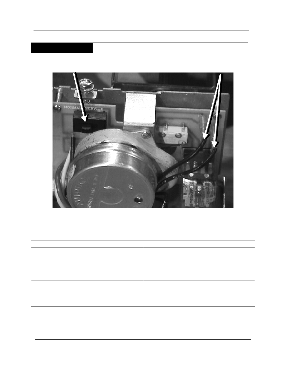
STEP 6. PC BOARD/MOTOR TEST. Check for 24 VAC between the two motor lead
terminals of the PC board. Disconnect the wires for this test.
IF
THEN
24 VAC is not present:
• Replace the board (AOS part # 6522)
and go to step 7. The board and relay
are one piece. Regardless of which
part is defective, both parts should be
changed.
Voltage is present:
•
This verifies that the motor is receiving
power but not closing the damper.
•
Replace the motor (AOS part # 6521)
and go to step 7.
Note: The service switch may be used to bypass the damper, while waiting for a replacement part.
WARNING - In the event of damper motor failure, verify that the damper is in the "open"
position before utilizing the service switch. (BTR Series 106/107 and some prior series –
changed from momentary push button to service switch).
Service Switch
Motor Lead
Terminals