3 output signals – FEC AFC1500 User Manual
Page 15
AFC1500 Multi-2 Unit Hardware Manual (Rev. 2)
PAGE 4 - 15
Chapter 4: Installation & Wiring
(Continued)
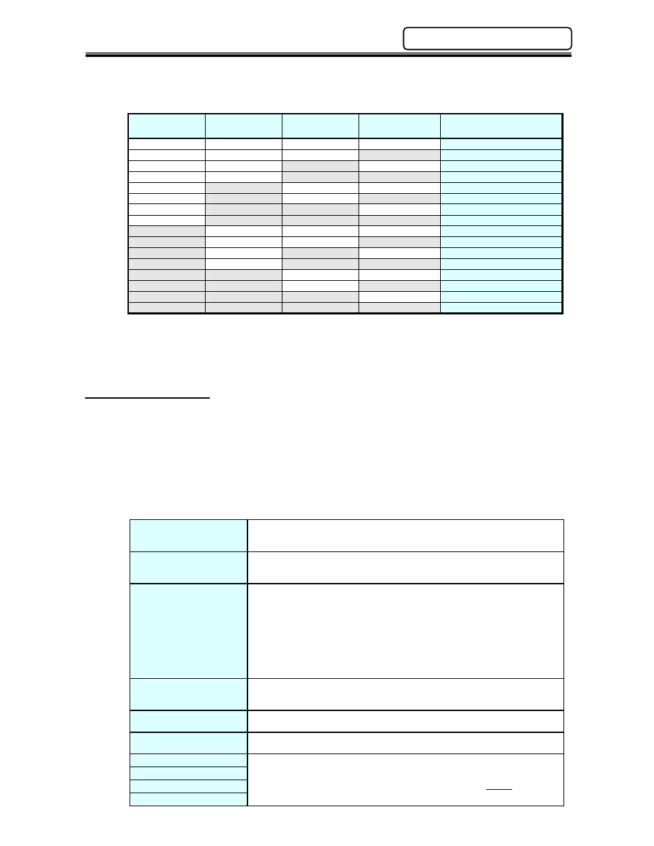
[Table 1 – Sequence Selection]
Sequence
Select 3
Sequence
Select 2
Sequence
Select 1
Sequence
Select 0
Selected Sequence No.
OFF
OFF
OFF
OFF
1
OFF
OFF
OFF
ON
2
OFF
OFF
ON
OFF
3
OFF
OFF
ON
ON
4
OFF
ON
OFF
OFF
5
OFF
ON
OFF
ON
6
OFF
ON
ON
OFF
7
OFF
ON
ON
ON
8
ON
OFF
OFF
OFF
9
ON
OFF
OFF
ON
10
ON
OFF
ON
OFF
11
ON
OFF
ON
ON
12
ON
ON
OFF
OFF
13
ON
ON
OFF
ON
14
ON
ON
ON
OFF
15
ON
ON
ON
ON
16
4.7.3 Output Signals
The list below contains a description of the output signals available on the I/O interface. Further
output mapping can be found in the individual interface information (See Chapter 5). The
Multi-2 Unit is capable of providing over 570 Output signals to indicate the status of the Multi-2
Unit and of all the AFC1500 SAN Controllers connected to it (up to 31 controllers). These
signals are user configurable using the AFC User Console Software and may be programmed
on any designated output bit.
Main Multi Unit Output Signals
Total Reject
Output when the fastening result is a REJECT. Indicates that one or more
spindles have failed achieving the fastening limits. This output remains active
until the START signal or RESET signal is input.
Total Accept
Output when the fastening result is a ACCEPT. Indicates all spindles are
within fastening limits. This output remains active until the START signal or
RESET signal is input.
Abnormal
Output when an Abnormal condition occurs. This signal indicates that the
System has detected an internal fault, and can no longer proceed. The fault
maybe generated from a connected spindle during a self-check function.
Check the individual spindle status to identify which spindle is reporting the
abnormal condition. (see AFC1500 Operation Manual for troubleshooting)
The spindle reporting an abnormal may be bypassed to resume normal
operation, however, the bypassed spindle will be ignored and not run while in
bypass. An Abnormal condition must be corrected before the System will
resume normal operation. The RESET signal clears the abnormal condition.
Ready
Output when the system is in the READY condition. Indicates system is ready
to operate, and inputs are enabled. This signal is inactive (off) when the
BUSY output is active (on).
Busy
Output after a START signal is received, and active until the fastening cycle is
complete and the READY signal is output.
End
Output when a fastening cycle is complete. Remains active until the START,
RESET or REVERSE signal is input.
Sequence 0
Output confirmation of SEQUENCE SELECT 0~4 input selections.
Sequence bits are active according to what sequence is set from the
sequence select inputs. Used to confirm proper sequence before fastening
starts. Refer to Table 3.
Sequence 1
Sequence 2
Sequence 3