2 input signals – FEC AFC1500 User Manual
Page 14
AFC1500 Multi-2 Unit Hardware Manual (Rev. 2)
PAGE 4 - 14
Chapter 4: Installation & Wiring
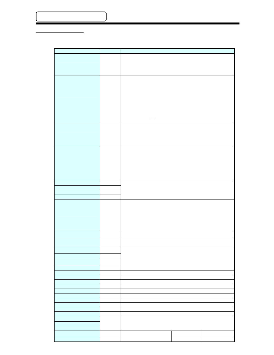
4.7.2 Input Signals
The list below contains a description of the Input signals available on the I/O interface. Further input
mapping can be found in the individual interface information (See Chapter 5).
Signal
Contact
Description
Emergency Stop
N.C.
Emergency Stop Input.
Signal MUST be Active to perform a fastening operation.
When this signal is inactive (off), all Multi-2 Unit operation ceases,
all spindles in motion will stop, and all communication ports &
input/outputs will be disabled.
Reset
N.O.
Reset Input.
When active (on), this signal will clear all spindle data and
discrete outputs. A Zero Check of all torque transducers will be
completed. During the Zero Check, the CHECK lamp will
illuminate, the READY signal will turn OFF, and the ACCEPT or
REJECT lamp will light to indicate the result of the Zero Check. If
the System has been disabled by an Abnormal output, the
System will not return to normal operation until the Abnormal
condition has been corrected, and this signal has been input for
200~500ms. Do not input this signal between cycles as part of an
automatic cycle due to the potential for fastening data loss.
Reverse
N.O.
Reverse Spindle Rotation Input.
All spindles will rotate in an opposite direction (of fastening) for as
long as this signal is activated (on) and maintained. The Reverse
input functions the same as the reverse pushbutton on the front of
the Multi-2 Unit.
Start
N.O.
Start Cycle Input.
The Start input automatically resets the previous cycle, clears all
data to zero, and initiates the next fastening cycle. The start input
requires a pulse of 200~500 milliseconds if the Multi-2 Unit is set
up for AUTOMATIC Start input. If it is set up for DEADMAN
(hand-held operation) input, the Start input must be maintained
"on" for the entire cycle. Typically this signal is held on until
confirmation of the “Busy” signal is received.
Sequence Select 0
N.O.
Sequence Select Input.
These 5 inputs form a binary code which is capable of selecting
up to 16 different operation sequences. Refer to Table 1. (Can be
used for part model selection)
Sequence Select 1
N.O.
Sequence Select 2
N.O.
Sequence Select 3
N.O.
Cycle Count Up
N.O.
Cycle Count Input.
The System cycle counter will increment each time this signal is
input if the CYCLE COUNT UP is set to PLC SIGNAL in the
Multi-2 Unit. The Cycle Count input requires a pulse of 200~500
milliseconds to increment the counter. If the CYCLE COUNT UP
is set to AUTO, the cycle counter increments automatically at the
end of every fastening.
Cycle Count Clear
N.O.
The internal cycle counter is reset when this signal is input.
Resetting the counter value requires a 200~500ms pulse.
Self Check Disable
N.O.
Disables the Calibration & Zero Level check that automatically is
performed at the start of each cycle
INPORT 1
N.O.
External Sequence Input.
These four (4) signals are external inputs to the fastening
sequence. When a [PLC INPUT WAIT] instruction is programmed
in the fastening sequence, it will stop until the designated external
input is active.
INPORT 2
N.O.
INPORT 3
N.O.
INPORT 4
N.O.
BYPASS Spindle No.1
N.O.
Bypass’s spindle #1 - Spindle is ignored as if it does not exist.
BYPASS Spindle No.2
N.O.
Bypass’s spindle #2 - Spindle is ignored as if it does not exist.
BYPASS Spindle No.3
N.O.
Bypass’s spindle #3 - Spindle is ignored as if it does not exist.
BYPASS Spindle No.4
N.O.
Bypass’s spindle #4 - Spindle is ignored as if it does not exist.
BYPASS Spindle No.5
N.O.
Bypass’s spindle #5 - Spindle is ignored as if it does not exist.
BYPASS Spindle No.6
N.O.
Bypass’s spindle #6 - Spindle is ignored as if it does not exist.
BYPASS Spindle No.7
N.O.
Bypass’s spindle #7 - Spindle is ignored as if it does not exist.
BYPASS Spindle No.8
N.O.
Bypass’s spindle #8 - Spindle is ignored as if it does not exist.
BYPASS Spindle No.9
N.O.
Bypass’s spindle #9 - Spindle is ignored as if it does not exist.
BYPASS Spindle No10
N.O.
Bypass’s spindle #10 - Spindle is ignored as if it does not exist.
Data Select 0
These 3 inputs form a binary code to select up to 8 Output Data
Banks. Used for Digital I/O interfaces. NOTE: Not used for
Fieldbus interfaces. [See Table 3 on Page 5-12]
Data Select 1
N.O.
Data Select 2
Input Signal Power
Common for input signal.
Sink Type
+24V
Input Signal Power
Source Type
+0V