Operational theory 2.0, Teledyne analytical instruments – Teledyne 514 - NDIR analyzer User Manual
Page 19
2–7
Operational Theory 2.0
Teledyne Analytical Instruments
A Business Unit of Teledyne Electronic Technologies
Circuit components C1, D3, and D4 provide stable internal power to
the rest of the controller circuitry.
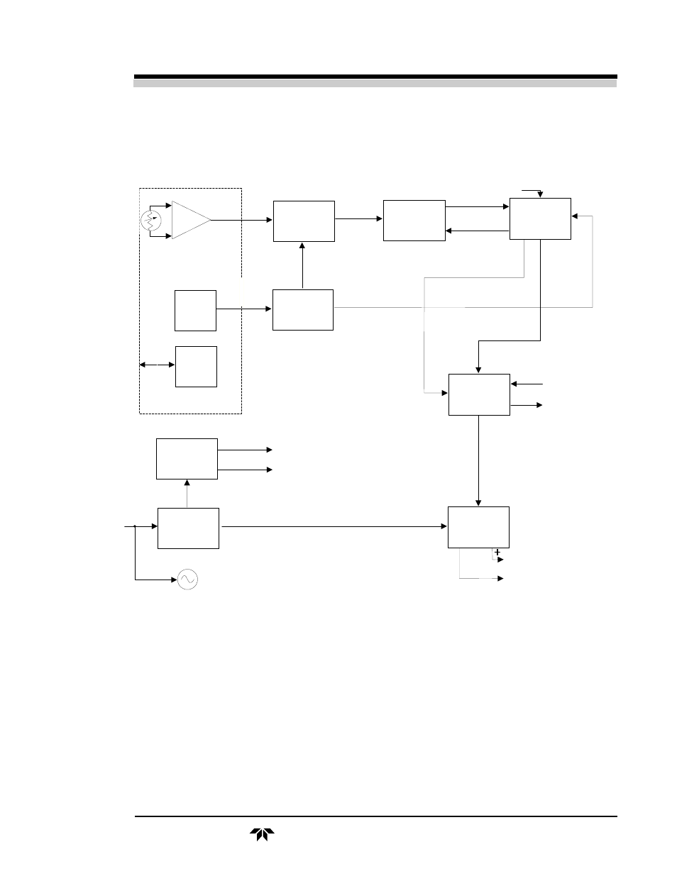
Figure 2-4. Detector Module - Block Diagram
Operating controls for the analysis section are located on the door
casting of the power module enclosure. In the general purpose configura-
tion, these controls include the POWER ON/OFF switch, the MEAS/REF
switch to select the measuring or reference peak voltage to be fed to the
local meter driver, ZERO control, and the NORM/ZERO switch, which
operates in conjunction with the MEAS/REF and ZERO controls.
When used with the explosion-proof control module, the NORM/REF
and NORM/MEAS switches are used on the module instead of the MEAS/
REF switch. A NORM/ZERO switch is also included.
PbS
Detector
Preamplifier
Video
Signal
Clamp
Clamped
Video
Switch
Driver
Filter
Position
Sensor
C
la
m
p
in
g
Sw
itc
h
Tim
in
g
Sig
na
l
To
Power
Module
Heater
&
Therm.
Detector
Compartment
Power
Supply
15 VDC
24 VDC
Power
Transformer
Chopper
Motor
115 VAC
60 Hz
Input
E-to-I
Converter
To Control Module
10 to 18 mA (Nominal Value)
C
o
m
.
0
to
0.4
VD
C
Fu
llS
c
a
le
Log
Amplifier
Coarse
Zero
Control
From
Power
Module
Re
f.
Le
ve
l
(+
9
VD
C
)
Switching Signals
(S, S', P, P')
M
e
a
s.
Le
ve
l
(+
9
VD
C
)
Elec. Sig.
Sw. & Peak
Level Detect.
Manual Peak Balance
Video
Ref. Level
AGC
To Meter
Filter Pos.
Signal
(Gate Pulse)