Operational theory 2.0 – Teledyne 514 - NDIR analyzer User Manual
Page 17
2–5
Operational Theory 2.0
Teledyne Analytical Instruments
A Business Unit of Teledyne Electronic Technologies
NORM/ZERO switch on the power module set to the NORM position, the
meter will provide a constant readout of either the reference level or the
measuring level. During calibration periods, the ZERO switch control may
be used to monitor the signal into the E-to-I converter, and if a known zero
sample is applied, then the ZERO potentiometer may be varied to ensure
zero output to the control unit.
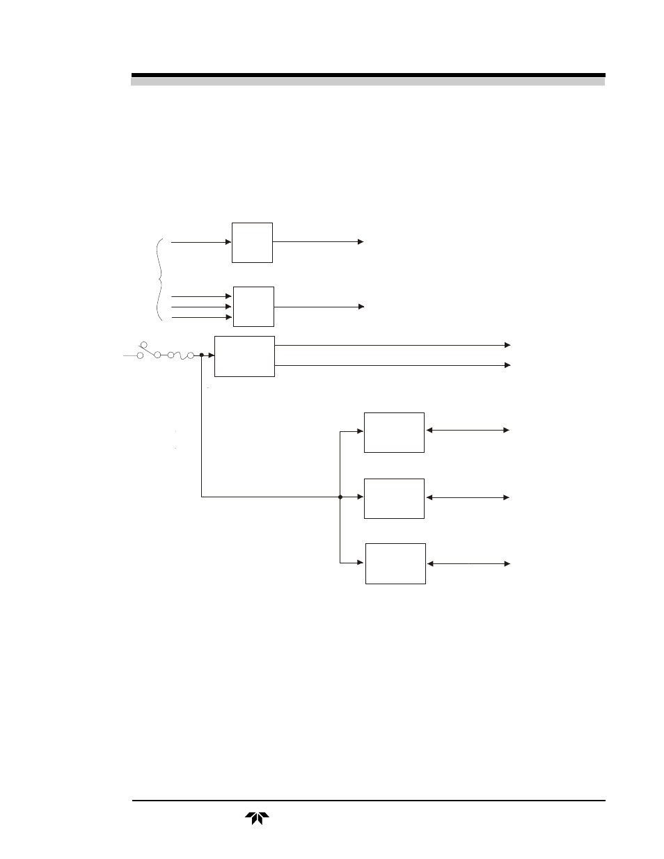
Figure 2-3.
Power Module - Block Diagram
All of the temperature controller circuit cards for the analyzer are
located in the power module. The schematic diagram for these circuits is
shown in dwg. B-15016.
The purpose of the time-proportional temperature controllers is to sense
the temperature in the compartment or volume to be controlled and, at a rate
of approximately twice per second, turn on the heater(s) for a specified
portion of the time cycle, depending upon how much heat is needed. When
15 VDC
Coarse
Zero
Control
Selector
Switch
MEAS
REF
ZERO
Power
Line Voltage
Regulator
Transformer
5A
S1
115 VAC
60 Hz
Input
Fr
om
D
et
ect
o
r M
od
ul
e
Preheater
Temp.
Control
Sample
Module
Temp.
Control
Detector
Module
Temp.
Control
Thermistor
and Heater
Thermistor
and Heater
Thermistor
and Heater
To Log Amplifier
To Meter Driver
115 VAC to
Source Module
115 VAC to
Detector Module