Teledyne 4020 - Hydrocarbon analyzer User Manual
Page 31
Total Hydrocarbon Analyzer
Installation
Teledyne
Analytical
Instruments
15
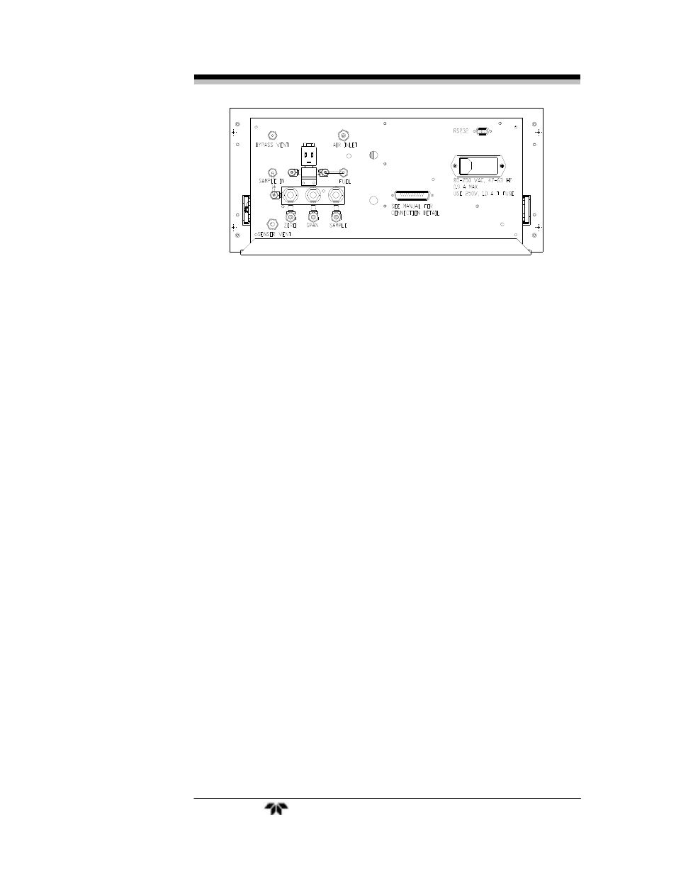
Figure 3-1: Gas Connections
Gas connections to the instrument are made at the 1/8”or 1/4”
stainless steel tube fittings provided on the rear panel. Note that the
Purge and Sensor Vent fittings are 1/4” while all other gas connections
are 1/8”.
It is recommended that all gas tubing leading to the connections on
the back of the analyzer be of the coiled type. This will facilitate sliding
the unit out of the case without disconnecting the gas supply to the
analyzer.
Before tubing is connected to the system, it must be decontaminated
to rid it of hydrocarbon deposits. Using a small torch, heat each length
of tubing, while passing nitrogen through it, until it glows red. Begin at
the nitrogen source end and proceed down the length of the tube,
“chasing” the red glow (and hydrocarbon deposits) down to the open
end of the tube. Cap tubing while not in use with suitable non-
contaminating caps.
All sample, calibration, and supporting gas lines which deliver gas to
the analyzer must be decontaminated before connection; vent lines do not.
When connecting the various gas lines to the system, be absolutely
certain that no “dead ends” are left; that is, no unused branch lines
should be left capped off, where pockets might form of material that is
not representative of the current contents of the line, or which might
keep contaminants from being purged out of the system.
Note: If different background gases are being used, the user
must supply the necessary valves and any associated
switching equipment for delivering the correct
sample/background gas combination to the analyzer.