Teledyne 3190 - OEM trace oxygen analyzer User Manual
Page 21
3-3
Trace Oxygen Analyzer
Installation 3
Teledyne Analytical Instruments
For special applications the Micro-Fuel Cell may also be of a different
type than the standard A-2C, B-2C or Z-2C unit. If this is the case, the
pertinent cell specifications will be given in the addendum.
3.2.3
Installing the Micro-Fuel Cell / Cell Block Orientation
A Micro-Fuel Cell is included as a separate item. It must be installed
prior to instrument use.
Also, once it is expended, or if the instrument has been idle for a
lengthy period, the Micro-Fuel Cell will need to be replaced.
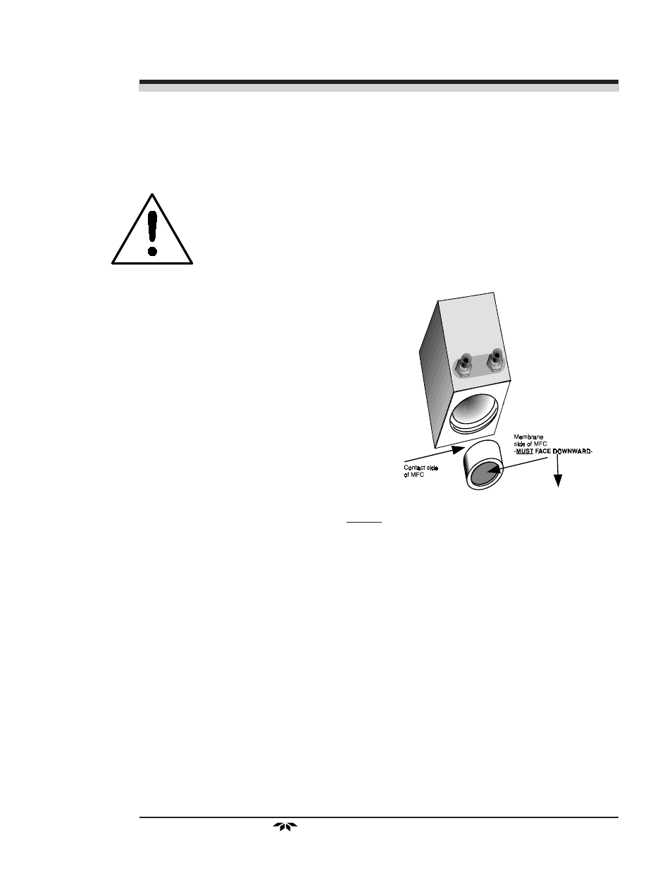
Important Installation Note!
During the Installation and/or Replacement of the MFC, Membrane
surface MUST ALLWAYS FACE DOWNWARD, and the Contact side of
the Membrane, MUST be placed FIRST into Analysis Unit.
The reason for proper Installation/Replacement is, if any bubble that
develops as the electrolyte dries out will be directed by the gravity away
from the membrane.
To install or replace the Micro-Fuel Cell, follow the procedures in
Chapter 5, Maintenance.
3.3
Electrical Connections
Figure 3-1 shows the two alternate Model 3190 rear panels. The first
illustration shows the AC powered version, and the second illustration shows
the DC powered version. The difference between them is the power connec-
tions. Both versions have identical connections for the External Probe, the
alarms, and for the digital and analog concentration outputs. For detailed
pinouts, see the wiring/interconnection drawings in the Drawings section at
the rear of this manual.