Teledyne 3190 - OEM trace oxygen analyzer User Manual
Page 18
2-6
2 Operational Theory
Model 3190
Teledyne Analytical Instruments
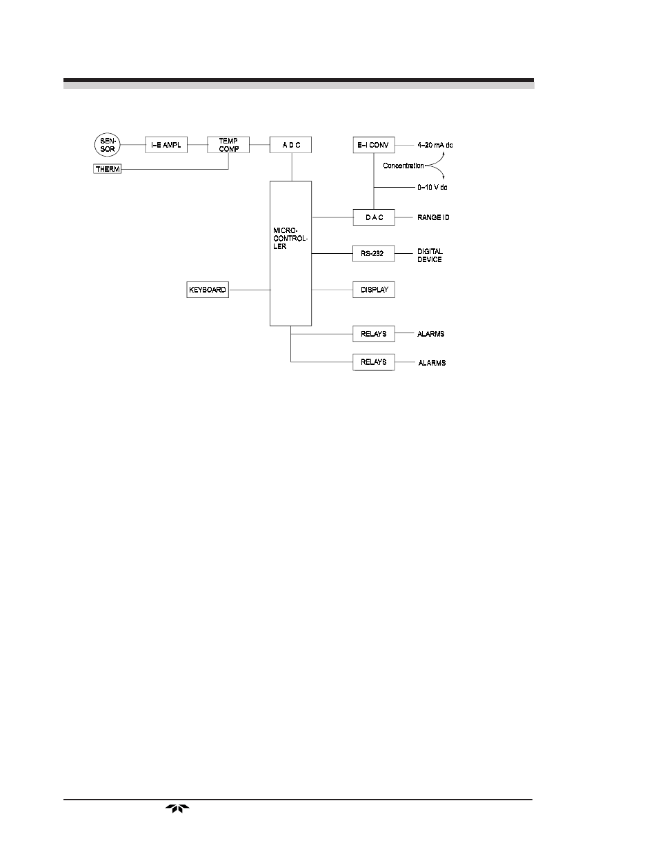
Figure 2-3: Block Diagram of the Signal Processing Electronics
In the presence of oxygen the cell generates a current. A current to
voltage amplifier (I–E AMPL) converts this current to a voltage.
The second stage amplifier (TEMP COMP) supplies temperature
compensation for the oxygen sensor output. The temperature compensation
amplifier incorporates a thermistor (THERM) that is physically located in
the cell block. The thermistor is a temperature dependent resistance that
changes the gain of the amplifier in proportion to the temperature changes
in the block. This change is inversely proportional to the change in the cell
output due to the temperature changes. As a result there is negligible net
change in the signal due to temperature changes once the sensor comes to
equilibrium. See Specifications in the Appendix.
The output from the temperature compensation amplifier is sent to an
analog to digital converter (ADC), and the resulting digital concentration
signal is sent to the microcontroller.
The digital concentration signal along with input from the front panel
buttons (KEYBOARD) is processed by the microcontroller, and appropri-
ate output signals are directed to the display, alarm relays, and RS-232
output. The same digital information is also sent to a 12-bit digital to
analog converter (DAC) that produces the 0-10 V dc analog concentration
signal and the 0-10 V dc analog range ID output. A current to voltage
converter (E–I CONV) produces the 4-20 mA dc concentration signal.