SPP Pumps Thrustream User Manual
Page 7
Operators Instructions for Horizontal
Standard Thrustream Centrifugal Pumps
Manual No/Rev
W12-003E / 6
Our policy is one of continuous improvement and we reserve the right to alter specifications at any time
Page 7 of 28
freely by hand by turning the shaft.
If the pump has been in storage, remove any
protective coatings. If the bearing housings
were filled with grease remove the bearing
housings, clean, and re-lubricate the bearings.
4.6
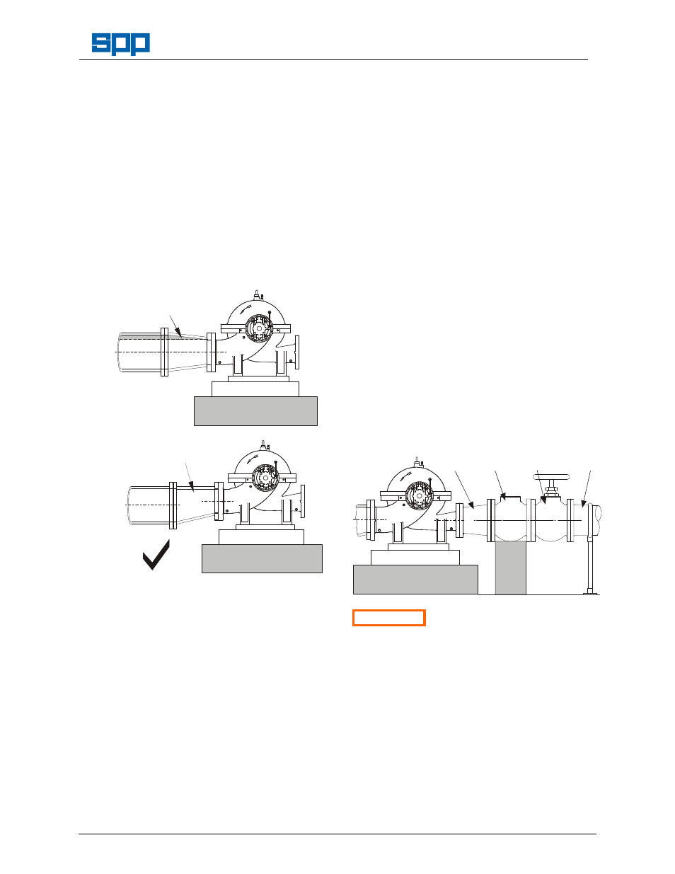
Suction Pipework
The run of suction pipework must be such that
air can NOT become trapped where it would
be drawn into the pump on starting. The bore
of the suction pipe is recommended to be one
or two sizes larger than the pump suction
branch and reducers if used must be eccentric
to eliminate the possibility of an air pocket
being formed.
CONCENTRIC REDUCER
WILL TRAP AIR IN THE
SUCTION PIPE
Foundation Plinth
X
FLAT TOP REDUCER
WILL NOT TRAP AIR IN
THE SUCTION PIPE
Foundation Plinth
Bends in the suction pipeline should be as
large as possible, the pipe made as short and
as straight as possible and all joints must be
fully airtight. A gradual rise in the suction
pipeline is recommended to prevent formation
of air pockets. If fitting a foot valve, it should
have a free area of one and a half times the
area of the suction pipe.
Where pumping water at temperatures above
70°C, care must be taken to ensure that
enough pressure is available at the impeller
entry to prevent vaporisation. Expansion
joints are recommended to prevent strain on
the pump casing.
An appropriate fine strainer is recommended
to prevent foreign matter from being drawn
into the pump. A screen or basket strainer
may also be required to hold back larger
items. These should be sized to maintain the
flow through them to below 0.6 m/s.
The suction pipe work must be flushed clean
to ensure that site debris is not drawn into the
pump when it is commissioned.
4.7
Discharge Pipework
The bore of the discharge pipe should ideally
be sized to ensure a flow velocity of 2.5 to 3
m/s is not exceeded. This is usually one size
larger than the discharge branch. Pipework
should be as short and straight as possible to
reduce friction head loss.
A non-return valve is usually fitted to prevent
the pump from excessive backpressure and
reverse rotation and a discharge valve is
usually fitted for isolation purposes to allow for
inspection and maintenance on the pump.
Where adverse suction conditions may cause
the pump to lose its prime, the use of an
external automatic priming device, such as a
vacuum pump, is recommended.
The suction and discharge pipework must be
independently supported and positioned such
that no excessive forces and moments are
exerted on the pump flanges.
INCREASER
CHECK
VALVE
DISCHARGE
VALVE
DISCHARGE
PIPE
Foundation Plinth
Check
Valve
Support
ATTENTION Failure to support suction and
delivery pipework may result in distortion of
the pump casing, with the possibility of early
pump failure.
4.8
Guards
If guards have been removed to install packing
or to check mechanical seal connections, they
MUST be replaced to maintain safe operation
of the pump. Refer to the General
Arrangement drawing for specific fixing
methods for the guarding supplied.