SPP Pumps Thrustream User Manual
Page 18
Manual No/Rev
W12-003E / 6
Operators Instructions for Horizontal
Standard Thrustream Centrifugal Pumps
Our policy is one of continuous improvement and we reserve the right to alter specifications at any time
Page 18 of 28
10. Fit washers and nuts (41A & 41F) to retain the
support frames.
11. For soft packed pumps: Fit the packing (51),
lantern rings (46) and glands (50) in position
as per instructions in section 6.2.
12. Fit the mechanical seals to the shaft as per
the manufacturer’s instructions.
13. Fit new oil seals into the support frames (61)
ready for assembly of the bearings and
bearing housings.
14. Heat the non-drive end bearing (66) to
approximately 100
0
C (212
0
F) using bearing
hot-plate, induction heater or oven. NOTE:-
Do not exceed 120
0
C (248
0
F).
15. Slide the heated bearing onto the shaft to abut
the shoulder
16. Place the locking washer (75F) onto the shaft
and screw on the bearing lock nut (75).
17. Fit and tighten the bearing locknut to 300 Nm
and lift the tab of the lock washer.
18. Repeat paragraphs 14 to 16 for the drive end
bearing (67).
19. Cool the bearings to room temperature and
coat both sides with two/three ounces of
recommended grease.
20. Coat the inside of the bearing housings (A62)
with grease and slide into place over each
bearing.
21. Secure the bearing housings (A62 & B62) to
the inserts (41) with four hexagon screws &
washers (61A & 61F).
22. Check and install the dowel pins (23A) to
locate the case wear rings (23).
23. Place the rotating assembly into the pump
casing bottom half (B1). Correct any
excessive ‘O’ ring twisting or buckling. Check
that the impeller is centralised in the casing
and that there are no rubs.
24. Install casing gasket (1U) with a light coat of
commercial cup grease on both gasket
surfaces. Carefully align the inner edge of the
gasket with the insert ‘O’ rings.
25. Lower the upper half casing (Al) into place and
install casing joint nuts (1F).
26. NOTE: When installing upper half casing,
make sure that the ‘O’ rings (53R) are not cut
or pinched and that the gasket is hard against
the ‘O’ rings.
27. Insert casing joint dowels (1C) and drive them
home. Tighten the joint nuts (1F) to the
specified torques
Thread Size
lb/ft
Nm
M16
120
160
M20
260
360
M24
440
600
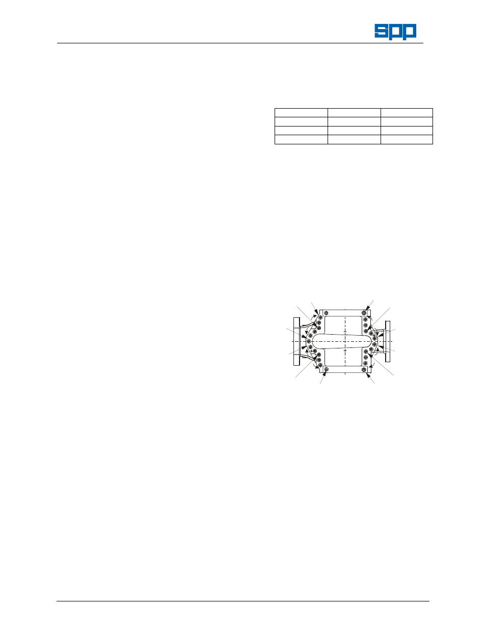
28. Tighten the case screws in the following
sequence:
a) Tighten the four 'corner' screws marked 1,
2, 3 and 4.
b) Work outward along shaft axis toward the
stuffing
boxes
in
opposite
quarters
tightening screws in regions 5, 6, 7 and 8.
c) Work outward along the branch and in
opposite quarters tightening screws in
regions 9, 10, 11 and 12.
d) Repeat the whole sequence (a to d).
1
2
3
4
6
8
7
5
9
10
11
12
29. Check that the shaft turns freely by hand.
30. Top up the bearing lubrication by applying
several strokes with a grease gun.
31. The pump is now ready for re-coupling to the
motor and re-commissioning.