SPP Pumps Thrustream User Manual
Page 17
Operators Instructions for Horizontal
Standard Thrustream Centrifugal Pumps
Manual No/Rev
W12-003E / 6
Our policy is one of continuous improvement and we reserve the right to alter specifications at any time
Page 17 of 28
2
Ensure that all parts to be refitted (especially
new parts) are free from burrs, with screw
threads and abutting faces clean and free
from damage.
3
Examine 'O' and 'V' rings and renew if
showing wear, damage or deterioration.
Rotor Reassembly
1
Lightly smear the shaft (71) with clean good
quality grease.
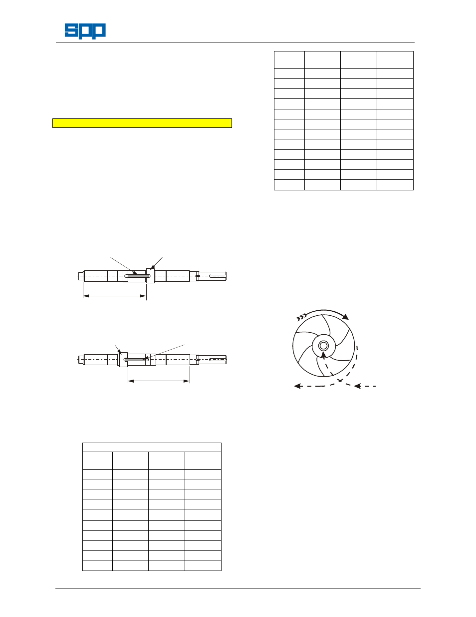
Note The position of the impeller key (116) and the
locked sleeve (B47) or impeller nut (B21) is
governed by the direction of rotation of the
pump. For clockwise pumps they are fitted
at the drive end of the shaft key slot and
for counter-clockwise pumps they are at
the non-drive end.
For clockwise rotation:
DIMN. A
IMPELLER
KEY
DRIVE END IMPELLER
NUT OR SLEEVE
For counter-clockwise rotation:
DIMN. B
IMPELLER
KEY
NON-DRIVE END IMPELLER
NUT OR SLEEVE
Where the location was not marked, and for
non-standard pumps with mechanical seals
please refer to the pump section drawing
supplied or to SPP Pumps Ltd for dimensions
A or B.
For Standard Soft Packed Pumps
Size
Pump
Dimn. A
mm
Dimn. B
mm
50/38
(TE05A)
283
287
80/38
(TE08A)
283
287
65/24
(TB06A)
283
287
80/24
(TB08A)
283
287
125/24 (TB12A)
337
341
150/24 (TB15A)
337
341
125/29 (TC12A)
283
287
80/30
(TD08A)
283
287
100/30 (TD10A)
283
287
125/30 (TD12A)
337
341
Size
Pump
Dimn. A
mm
Dimn. B
mm
100/24 (TB10A)
355
359
250/24 (TB25A)
415
419
150/30 (TD15A)
355
359
200/30 (TD20A)
415
419
250/30 (TD25A)
415
419
100/38 (TE10A)
355
359
125/38 (TE12A)
355
359
150/38 (TE15A)
355
359
200/38 (TE20A)
419
423
250/38 (TE25A)
419
423
150/48 (TF15A)
419
423
200/48 (TF20A)
419
423
2
Screw the locked sleeve (B47) or impeller nut
(B21) onto the shaft (71) to the initial setting
dimension shown in the table above. Turn the
nut or sleeve to the nearest slot to align with
the keyway.
3
Place impeller key (116) into keyway and tap
the stepped end right home under impeller
locking nut or sleeve.
4
Check the impeller for correct direction of
rotation and slide onto shaft.
5.
Screw free impeller locking sleeve (A47) or
nut (A21) onto shaft to retain the impeller
against the locked impeller nut or sleeve.
6.
Position the casing wear rings (23) the correct
way round and with dowel holes at the bottom
and slide onto the impeller.
7.
For component mechanical seals fit the
rotating elements in position at this stage.
7.
Lightly grease and carefully fit new ‘O’ rings to
the inserts.
8.
Slide the inserts (41) on to the shaft with the
guide vane at the top position.
9.
Locate the support frames in position and
insert the lantern rings (46) and the glands
(50) or the throttle bushes (45) and cartridge
mechanical seals (52), then slide into position
over the shaft to abut the inserts.