SPP Pumps Thrustream User Manual
Page 15
Operators Instructions for Horizontal
Standard Thrustream Centrifugal Pumps
Manual No/Rev
W12-003E / 6
Our policy is one of continuous improvement and we reserve the right to alter specifications at any time
Page 15 of 28
Preparation for Removal of the Rotating Assembly
Disconnect the motor coupling.
For pumps fitted with mechanical seals, refer
to the seal manufacturer’s instructions and
lock the seal before removing the retaining
screws (52A) and sliding the seal back from
the face of the insert (A53).
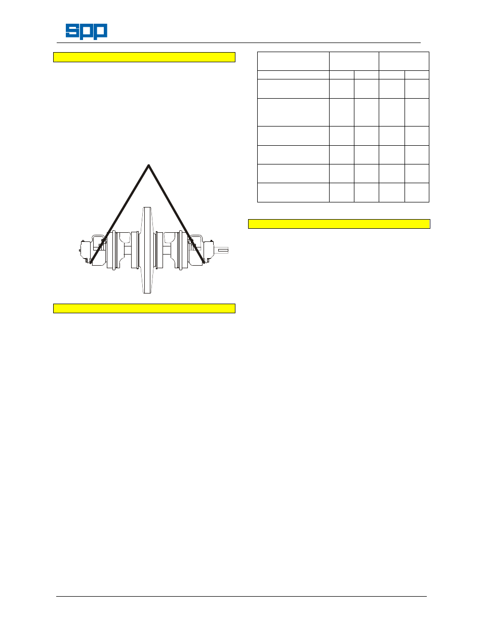
Provide a suitable lifting strap and support the
weight of the rotating assembly thus:
Removal of the Rotating Assembly Procedure
1.
Tap the inserts (53) with a soft-faced hammer
to break the seal between the insert and the
bottom half casing (B1).
2.
Lift the rotating element out of the bottom half
casing.
3.
Lift the rotating assembly clear of the bottom
half casing and support the shaft on suitable V
blocks with the impeller clear of the work
surface.
4
If necessary, remove the case wear ring
dowels (23A) from the bottom half casing
(B1).
5
With feeler gauges, check the clearance
between the case wear rings (23) and the
impellers (21), compare clearance with the
figures below.
Note Increase in the wear ring clearance allows
increased internal leakage with resultant loss
of pump performance, head and efficiency.
When the clearance is double the original
clearance, it is recommended that new wear
rings are fitted. It is permissible to run the
pump with increased clearance due to wear
but the loss of pump efficiency will significantly
increase the pump running costs.
Wear Ring
Clearance
Diametral
mm
Radial
mm
Pump Size :
Min
Max
Min
Max
65/24 80/24
80/30
0.180 0.302 0.090 0.151
50/38 80/38
125/29 100/30
100/24 100/38
0.210 0.350 0.105 0.175
125/24 150/24
125/30
0.230 0.370 0.115 0.185
150/30 125/38
150/38
0.240 0.401 0.120 0.200
150/48 250/24
200/30 250/30
0.260 0.421 0.130 0.210
200/38 250/38
200/48
0.280 0.441 0.240 0.220
Procedure to dismantle the Rotating Assembly
1.
Remove both bearing housings and bearings
as per the bearing replacement procedure
paragraphs 1 to 9.
2.
For soft packed pumps: Remove the nuts
(41C) and slide the glands (50) off the end of
the shaft (71) and remove the inserts (41 a &
B) complete with packing rings (51) and
lantern rings (46) and set aside for inspection.
3.
For pumps fitted with mechanical seals: Slide
the mechanical seal assemblies off the shaft
and set aside for inspection and remove the
inserts (41 A & B) complete with mechanical
seal (52) and throttle bush (45) and set aside
for inspection.
Impeller removal:
4.
If not already removed, remove the case wear
rings (23) and set aside for inspection and
measurement.
For Clockwise pump construction:
5.
Using a suitable ‘C’ spanner, unscrew and
remove the free - non-drive end sleeve (A47)
on a soft packed pump or free - impeller nut
(A21) on a pump fitted with mechanical seals.
Note Light tapping with a soft faced mallet may be
needed to free the impeller from the shaft, do
not damage the impeller if it is to be reused.
6.
Using suitable pullers or levers slide the
impeller (21) of the shaft (71) from the non-
drive end.
7.
Withdraw the impeller key (116) and unscrew
and remove the locked - drive end sleeve
(B47) on a soft packed pump or locked -