SPP Pumps Thrustream User Manual
Page 12
Manual No/Rev
W12-003E / 6
Operators Instructions for Horizontal
Standard Thrustream Centrifugal Pumps
Our policy is one of continuous improvement and we reserve the right to alter specifications at any time
Page 12 of 28
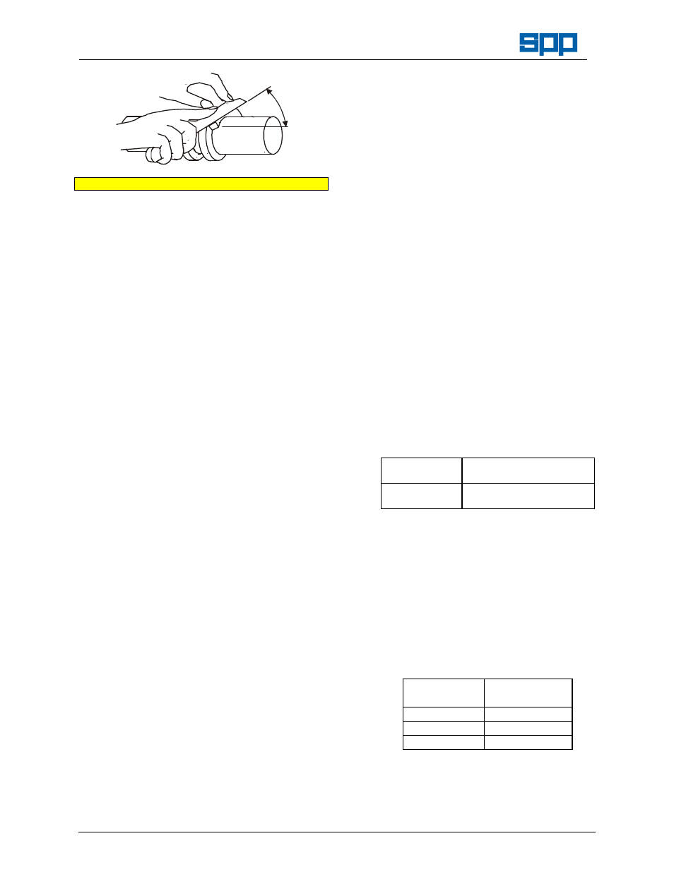
45
o
Repacking Procedure
10 Insert the first ring and tap it to the bottom of
the stuffing box. Each following ring should be
installed in the same manner and positioned in
the stuffing box so that the "split" is advanced
120°.
11 Install the lantern ring (46) in its proper
position to align with the seal lubrication
connection, allowing for movement of the ring
deeper into the box as the packing is
compressed.
12. When the all the rings have been inserted, the
last packing ring should not protrude from the
stuffing box face.
13. Slide the gland into the stuffing box and
ensure that it sits squarely against the last
packing ring. Fit the gland retaining nuts and
washers (41C & 41G) on the studs and tighten
evenly to finger pressure.
14. Start the pump as per paragraph 5.2, allow
pressure to increase to normal level and
ensure that air is not trapped in the pump
casing.
15. A soft packed gland must have slight steady
leakage, and this should start soon after the
pump reaches it’s normal operating pressure.
16. If gland leakage stops, the pump will overheat
leading to seal damage or premature pump
failure. If overheating is detected, the pump
must be stopped and allowed to cool and
when restarted, gland leakage should start.
17. If the pump overheats again, stop the pump
restart it again, do not slacken the gland
retaining nuts.
18. After the pump had been running for 10
minutes with steady leakage, tighten the gland
nuts by one sixth of a full turn. Continue to
adjust at 10-minute intervals, each time
evenly, by one sixth of a full turn, until leakage
is reduced to an acceptable level (30 drops
per minute minimum).
19. Excessive gland pressure will cause damage
by cutting off lubrication to the packing, and
the packing will burn and damage the
shaft/sleeve.
6.3
Maintenance of Mechanical Seals
Generally no maintenance is required on
mechanical seals. They should be replaced if
leakage occurs but if maintenance is required,
the manufacturer's information is given in
Appendix IIl.
For disassembly and assembly instructions for
pumps
fitted
with
internal
component
mechanical seals, please refer to separate
instructions that can be obtained from SPP
Pumps Ltd.
6.4
Bearing Lubrication
The ball bearings are supplied pre-loaded with
appropriate grease. A grease nipple and seals
are fitted to the bearing housing to ensure that
any surplus grease is trapped inside the
bearing housing.
It is important to know the weight of grease
delivered by each stroke your grease gun to
ensure application of the correct amount of
grease.
It is recommended that the drive end bearings
are topped up as per the Recommended
Maintenance Schedule in Section 6.
Recommended Grease Lubricant:
International
Standard
DIN 51825:
KP2 K-30
As Supplied with
a new pump.
TEXACO MULTIFAK ALL
PURPOSE EP2
Note Greasing points may be provided for the
bearings on the electric motor fitted, refer to
Appendix I for motor maintenance details.
6.5
Bearing Replacement
Ball bearings will provide satisfactory service
for their designed working life if they are
correctly lubricated and inspected at the
intervals shown in Section 6. - Recommended
Maintenance Schedule.
Bearing Specifications
Pump Shaft
Module
Ball Bearing
Reference No.
Module 1
6306
Module 2
6309
Module 3
6312
A suitable bearing puller is required for
removal of the bearings from the pump shaft.
If a puller is not available, a hammer and soft
metal drift may be used to tap evenly around
the circumference of the inner ring.