Installation – Fulton Reliance (RLN) High Efficiency Cooper Fin Boiler User Manual
Page 13
Questions? Call (315) 298-5121, or visit us online at www.fulton.com
SECTION 2
RLN-IOM-2012-1205
INSTALLATION
2-7
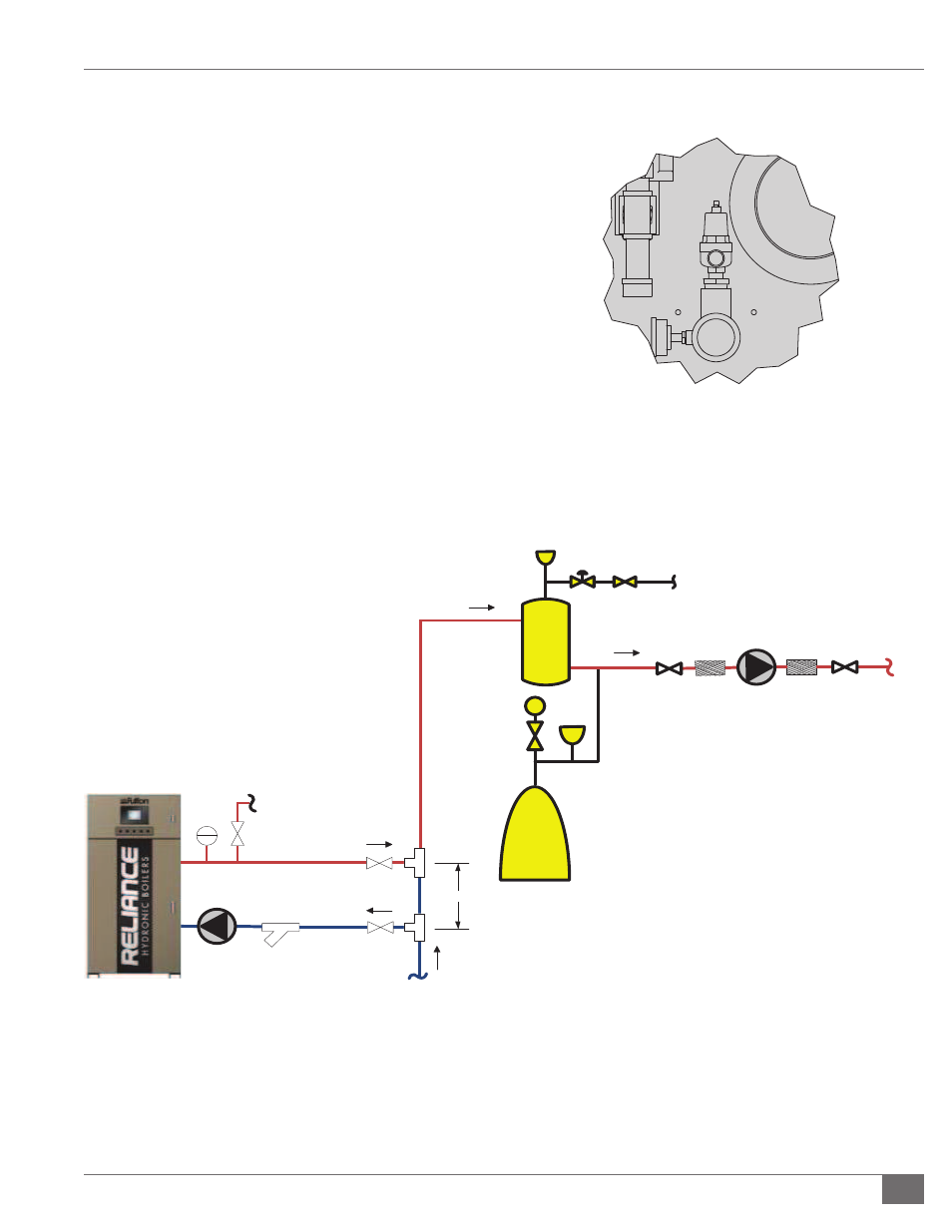
FIGURE 2 - SAFETY VALVE
Dedicated
Pump
T
Safety
Relief
Valve
Heating
Loop
Return
12"
Strainer
Cold Water
Supply
Air
Separator
PRV
P
Expansion
Tank
Hot Water
Heating
Loop Supply
System
Pump
Air
Sep.
be installed so the chilled medium is piped in parallel
with the boiler with appropriate valves to prevent the
chilled medium from entering the boiler. If the boilers
are connected to heating coils, located in air handling
units where they may be exposed to refrigerated
air circulation, such boiler piping systems shall be
equipped with fl ow control valves or other automatic
means to prevent gravity circulation of the boiler water
during the cooling cycle.
9. The boiler is not provided with a drain valve directly on
the boiler. A drain valve should be installed near the
system return (water inlet) connection to the boiler and
piped to a drain.
10. Before installing a Reliance boiler into a hydronic
loop, be sure that the system piping and any other
components of the system are clean and free of debris
and any foreign matter. The hydronic system should be
completely fl ushed prior to installing the boiler itself.
FIGURE 3 - SAMPLE PIPING LAYOUT: SINGLE BOILER WITH RETURN WATER TEMPERATURE >140 F (60 C)