Assembly, Service and adjustments – Poulan Pro PR625P_115587827 LAWN TRACTOR User Manual
Page 8
8
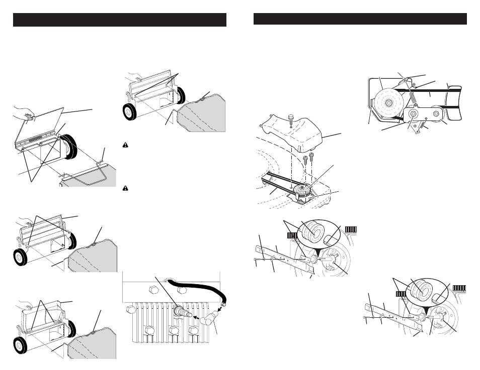
Hinge bracket
Formed tabs
Rear door
Grass
catcher
frame
Handle bracket hooks
Rear
door
Grass
catcher
handle
Catcher
frame side hook
ASSEMBLY
“FABRIC TOP” GRASS CATCHERS
ASSEMBLE/ATTACH GRASS CATCH ER
• Put grass catcher frame into grass bag
with rigid part of bag on the bottom.
• Slip vinyl bindings over frame.
NOTE: If vinyl bindings are too stiff, hold
them in warm water for a few minutes. If
bag gets wet, let it dry before using.
• Lift the rear door on the mower housing.
• For HINGE BRACKET mounted catcher,
place the grass catch er frame onto the
formed tabs on the rear door hinge
bracket.
• For HANDLE BRACKET mounted
catcher, place frame side hooks into
slots in handle brackets.
Rear door slots
Grass
catcher
han dle
Catcher frame hook
Pivot pins
Grass
catcher
handle
Catcher
frame hook
Rear
door
• For DOOR PIVOT PIN mounted catcher,
place the grass catcher frame hooks
onto the door pivot pins.
• For DOOR SLOT mounted catcher,
place the grass catcher frame hooks into
the slots of the rear door.
NOTE: The grass catcher is secured to the
lawn mower housing when the rear door is
lowered onto the grass catcher frame.
ALL GRASS CATCHERS
CAUTION: Under normal usage, the
catcher material is subject to de te ri o ra-
tion and wear and should, therefore, be
checked frequently for replacement. Any
replacement catcher should be checked to
ensure compliance with original man u fac-
tur er's spec i fi
ca tions.
CAUTION: Do not run lawn mower
with out the discharge guard (rear door),
approved grass catcher, clipping de fl ec tor
or mulcher plate in place. Never attempt
to operate mower with the dis charge guard
(rear door) removed or propped open.
SPARK PLUG BOOT
On some models a spark plug boot is
packed loose in the parts bag. If your
model has the boot, install on spark plug
wire and reconnect spark plug wire to
spark plug.
Spark plug
Boot
29
Drive cable anchor
Drive pulley
Housing holes
Drive belt
Idler arm
assembly
Belt
keepers
Hex nut
Return
spring
MODELS WITH GEARCASE-MOUNTED
BELT KEEPER:
• Remove drive cover and belt keeper.
• Remove belt from gearcase pulley.
• Turn lawn mower on its side. See
engine manual for proper direction of
turning over the engine.
• Remove blade and blade adapter.
• Remove belt from pulley of blade
adapter.
• Install new belt by reversing above
steps.
NOTE: Always use factory approved belt
to assure fi t and long life.
• Turn lawn mower on its side. See engine
manual for proper direction of turning
over the engine.
• Use a wood block between blade and
mower hous ing to prevent blade from
turning when re mov ing blade bolt.
NOTE: Protect your hands with gloves
and/or wrap blade with heavy cloth.
• Remove blade bolt.
• Remove blade, attaching hardware (bolt,
lock wash er, hardened wash er) and
blade adapter.
• Remove drive belt from engine pulley;
discard old belt.
• Install new belt by reversing above
steps.
NOTE: Always use factory approved belt
to assure fi t and long life.
• The recommended tightening torque is
35-40 ft. lbs.
IMPORTANT: Blade bolt is grade 8 heat
treated.
Belt
Drive
cover
Belt
keeper
Gearcase
pulley
Blade
bolt
Crankshaft
keyway
Hardened
washer
Lockwasher
Blade adapter
Key
Blade
Trailing edge
Belt
retainer
Blade
bolt
Crankshaft
keyway
Hardened
washer
Lockwasher
Blade adapter
Key
Blade
Trailing edge
Crankshaft
Belt
retainer
SERVICE AND ADJUSTMENTS
• Remove drive cable from anchor, then
detach it and return spring (if equipped)
from idler arm assembly.
• Remove idler arm assembly from hous-
ing by removing hex nut; then remove
drive belt from drive pulley, belt keepers
and idler arm assembly.
REAR WHEEL DRIVE MODELS:
MODELS WITH IDLER ASSEMBLY:
• Disconnect spark plug wire from spark
plug and place wire where it cannot
come in contact with plug.
• Remove screws retaining drive cover
(not shown); and remove drive cover
from lawn mower housing.