Operation, Service and adjustments – Poulan Pro PR625P_115587827 LAWN TRACTOR User Manual
Page 10
10
Remote
throttle
control
FAST
SLOW
CHOKE
(START)
OPERATION
The operation of any lawn mower can result in foreign objects thrown into the
eyes, which can result in severe eye damage. Always wear safety glasses
or eye shields while operating your lawn mower or performing any ad just-
ments or repairs. We recommend standard safety glasses or a wide vision
safety mask worn over spectacles.
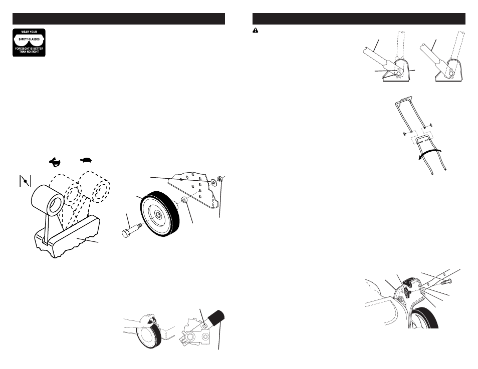
TO ADJUST CUTTING HEIGHT
ALL MODELS:
Adjust cutting height to suit your re quire -
ments. Me di um position is best for most
lawns. Raise wheels for low cut and lower
wheels for high cut.
NOTE: For shipping purposes, the rear
wheels on your lawn mower may not be
adjusted to the same position as the front
wheels. Before operating mower adjust all
wheels to the same cutting height.
“MANUAL” ADJUSTMENT
• Remove wheel, bolt, and hardware and
reassemble in desired adjustment hole.
• Reinstall wheel components in the same
order as they were before removal.
Tighten securely.
• Make sure all wheels are at same height.
“QUICK” ADJUSTMENT
• To change cutting height, squeeze adjuster
lever to ward wheel. Move wheel up or
down to suit your re quire ments. Be sure
all wheels are in the same setting.
NOTE: Adjuster is properly positioned when
plate tab inserts into hole in lever. Also, 9-
position adjusters (if so equipped) allow lever
to be positioned between the plate tabs.
Bolt
Flat washer
Wheel
3/8-16
Locknut
Spacer
LEVER BACKWARD
TO LOWER MOWER
LEVER FORWARD TO RAISE MOWER
Plate tab
Lever
HOW TO USE YOUR LAWN MOWER
ENGINE SPEED CONTROL
MODELS WITH REMOTE THROTTLE
Engine speed is con trolled by the throttle
control located on the upper handle.
• Move lever forward to FAST engine
speed for start ing and better bagging.
• Move lever backward for SLOW engine
speed.
• Some models have engines equipped
with a choke feature. Move the lever all
the way forward to the CHOKE position
when starting a cold engine.
NOTE: Be sure engine START/STOP
switch (if equipped) is in the ON po si tion.
MODELS WITH FIXED SPEED ENGINES
Engine speed was set at the factory for
optimum per form ance. Engine speed is
not adjustable.
27
SERVICE AND ADJUSTMENTS
TURN LOWER
HANDLE OVER
TO ADJUST HEIGHT
Mowing
position
Mowing
position
HIGH POSITION
LOW POSITION
Handle
bracket
Hairpin
cotter
Mounting
pin
CAUTION: Before performing any ser-
vice or adjustments:
• Release operator presence control bar.
• Make sure the blade and all moving
parts have com plete ly stopped.
• Disconnect spark plug wire from spark
plug and place wire where it can not
come in contact with plug.
LAWN MOWER
TO ADJUST CUTTING HEIGHT
See “TO ADJUST CUTTING HEIGHT” in
the Operation sec tion of this manual.
REAR DEFLECTOR
The rear defl ector, attached between the
rear wheels of your mower, is provided to
min i mize the possibility that objects will
be thrown out of the rear of the mower
into the operator's mowing position. If the
defl ector becomes dam aged, it should be
replaced.
DISCHARGE GUARD (IF EQUIPPED)
The discharge guard, attached to the side
dis charge opening of your lawn mower, is
pro vided to prevent the possibility of injury
re sult ing from objects being thrown out of
the dis charge opening into the operator
mowing position. If the dis charge guard
becomes dam aged, it should be replaced.
TO ADJUST HANDLE
“2 POSITION” HANDLES
The handle can be mounted in a high or
low po si tion. The mounting holes in the
bottom of lower handle are off center for
raising or lowering the handle.
• Remove upper handle and all parts at-
tached to lower handle.
• Remove hairpin cotters from lower
handle bracket mount ing pin.
• Squeeze lower handle in to remove it
from mounting pins.
• Turn lower handle over to raise or lower
handle.
• Squeeze lower handle in and position
holes onto mount ing pins on handle
bracket.
• Reassemble hairpin cotters onto pins.
• Reassemble upper handle and all parts
removed from lower handle.
3 POSITION “EZ” HANDLES
The handle on your lawn mower has three
(3) height positions - adjust to height that
suits you.
• Remove knob and carriage bolt on one
side of the lower handle.
• While holding handle assembly, remove
knob and car riage bolt from opposite
side, align hole in handle with desired
hole in handle bracket and reassemble
bolt and knob and tighten securely.
• Align opposite side of handle with same
positioning hole and secure with bolt and
knob.
Handle
bracket
Low
Knob
High
Medium
Bolt