Assembly, Service and adjustments – Poulan Pro PR625P_115587827 LAWN TRACTOR User Manual
Page 6
6
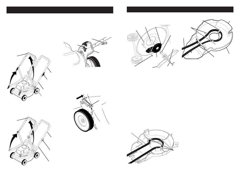
MOWING
POSITION
Lower handle
LIFT
UP
Operator
presence
control bar
Upper
handle
LIFT
UP
Handle
knob
“QUICK RELEASE” HANDLES
(ALL OTHER MODELS)
• Raise lower handle section to mowing
position and align holes in lower handle
with holes in handle brackets.
• Insert handle bolts through lower
handles and handle brackets; secure
with lower (“standard”) knobs.
• Remove protective padding, raise up-
per handle section into place on lower
handle and tighten both upper (“quick-
adjust”) knobs.
MOWING
POSITION
Lower handle
LIFT
UP
Operator
presence
control bar
Upper
handle
LIFT
UP
Upper handle
knob (“quick-
adjust”)
Lower handle knob
(“standard”)
2 POSITION / “ADJUSTABLE” HANDLES
• Raise handles until lower handle section
locks into place in mowing position.
ASSEMBLY
Handle pin
Handle
ad just ment
bracket
SQUEEZE
3 POSITION “EZ” HANDLES
• Raise lower handle section to operating
position and align hole in handle with
one of three height positioning holes.
• Insert handle bolt through handle and
bracket and secure with knob.
• Repeat for opposite side of handle.
3 POSITION “QUICK” HANDLES
• Raise lower handle section to operating
position and squeeze the bottom ends
of lower handle towards each other
until the pin in handle can be inserted
into one of the three height adjustment
holes.
ALL HANDLES
• Raise upper handle section into place on
lower han dle, remove protective padding
and tighten both handle knobs.
• Remove handle padding holding opera-
tor pres ence control bar to upper handle.
• Your lawn mower handle can be ad-
justed for your mowing comfort. Refer to
“ADJUST HANDLE” in the Service and
Adjustments section of this manual.
NOTE: For shipping purposes, the rear
wheels on your lawn mower may not be
adjusted to the same position as the front
wheels. Before operating mower adjust all
wheels to the same cutting height.
Handle
bracket
Knob
Bolt
31
Debris
shield
Drive
belt
Belt
retainers
SERVICE AND ADJUSTMENTS
Trailing edge
Crankshaft
Debris
shield
Screw
Blade
adapter
Hardened
washer
Lock-washer
Blade
bolt
Tab
Housing
hole
Debris
shield
Belt retainer
Belt
keepers
Drive
belt
Slot
Tab
7. Use a wood block between blade and
mower hous ing to prevent blade from
turning when re mov ing blade bolt.
NOTE: Protect your hands with gloves
and/or wrap blade with heavy cloth.
8. Remove blade bolt.
9. Remove blade, attaching hardware
(bolt, lock wash er, hardened wash er),
blade adapter and debris shield as one
assembly.
10. Remove drive belt from blade adapter
and debris shield; discard old belt.
TO REPLACE DRIVE BELT
1. Place new drive belt in the belt retainer
of the debris shield. Be sure to route
belt between belt keepers and through
slot as shown.
18" (45cm) HI-VAC MODELS:
21" (53cm) HI-VAC MODELS:
2. Route the other end of the new drive
belt through hole in housing.
3. Reattach debris shield to housing with
screw previously removed. Be sure tab
of debris shield is in gap of housing.
4. Position blade on the blade adapter
aligning the two (2) holes in the blade
with the raised lugs on the adapter.
5. Be sure the trailing edge of blade (op-
posite sharp edge) is up toward the
engine as shown.
6. Install the blade bolt with the lock
washer and hardened washer into
blade adapter and crankshaft.
7. Use block of wood between blade and
lawn mower housing and tighten the
blade bolt, turning clockwise.
• The recommended tightening torque is
35-40 ft. lbs.
IMPORTANT: Blade bolt is grade 8 heat
treated.
8. Return mower to upright position.
9. Install new drive belt into idler arm as-
sembly, then around the drive pulley.
Be sure belt is inside of belt keepers.
NOTE: Pulling on the drive belt (to install
it on the drive pulley) will cause the other
end of the belt to free itself from the debris
shield retainer and come into contact with
the pulley end of the blade adapter.
10. Reattach drive cable and return spring
to the idler arm assembly, then reattach
drive cable to anchor.
11. Reattach drive cover with screws previ-
ously removed.
12. Connect spark plug wire to spark plug.
6. Remove screw securing debris shield.
Note that the debris shield has a tab
which fi ts into a gap in the housing.