Maintenance, Operation – Poulan Pro PR625P_115587827 LAWN TRACTOR User Manual
Page 13
24
BLADES WITH ROUND HOLE:
• To check blade balance, drive a nail into
a beam or wall. Leave about one inch of
the straight nail ex posed. Place center
hole of blade over the head of the nail.
If blade is balanced, it should remain in
a horizontal position. If either end of the
blade moves downward, sharpen the
heavy end until the blade is balanced.
BLADES WITH “STAR” HOLE:
• To check blade balance, you will need
a 5/8" diameter steel bolt, pin, or a cone
balancer. (When using a cone bal anc er,
follow the in struc tions supplied with
bal anc er.)
NOTE: Do not use a nail for balancing
blade. The lobes of the center hole may
appear to be centered, but are not.
• Slide blade on to an unthreaded portion
of the steel bolt or pin and hold the bolt
or pin parallel with the ground. If blade
is bal anced, it should remain in a hori-
zontal po si tion. If either end of the blade
moves downward, sharpen the heavy
end until the blade is balanced.
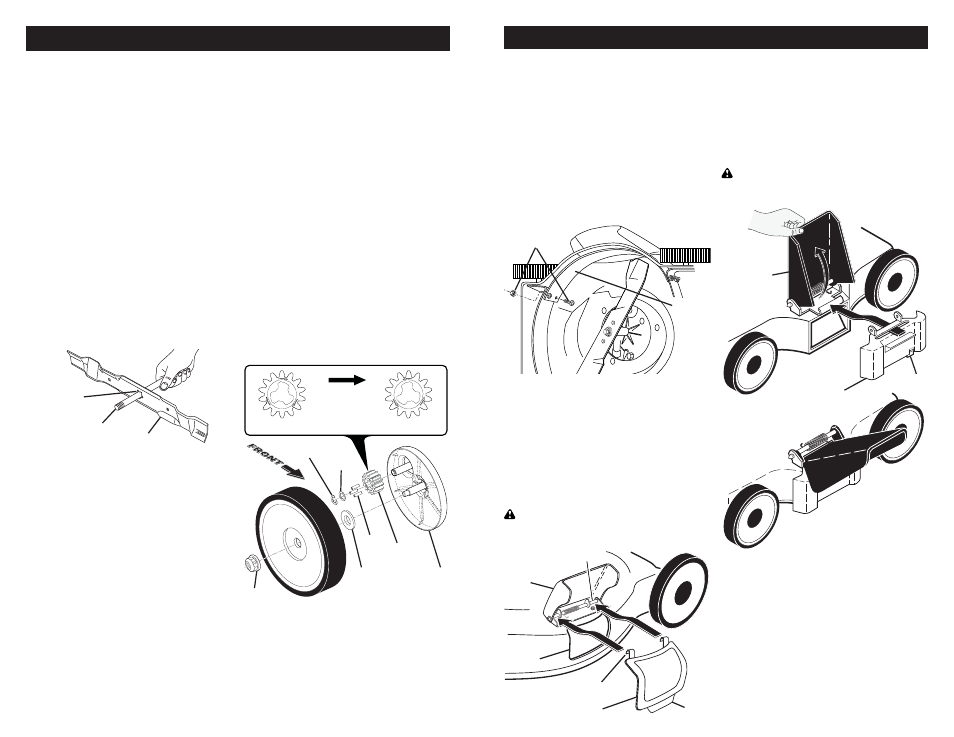
18" (45cm) HI-VAC MODELS ONLY:
1. Remove hubcaps (if equipped) and
locknuts.
2. Remove wheels from wheel ad just er
axles.
3. Remove any trash or grass cut tings
from inside the dust cover, pinion gear
and drive wheel gear teeth.
4. If you remove the pinion gears, wipe
clean with dry cloth. Re as sem ble
dry. Do not lubricate. Do not use oil or
grease.
IMPORTANT: The pinion gears (on both
sides of the mower) are the same, how-
ev er, they must be installed cor rect ly. If
in stalled in cor rect ly, the drive system will
not work.
5. There are arrows embossed on both
sides of the pinion gear. With the ar-
row at the top of the pinion, the arrow
must point towards the front of the
mower. If the arrow points to the rear
of the mower, turn the pinion around,
then assemble it to the mower.
6. Place wheels back on adjuster ax les.
7. Replace locknuts and hubcaps.
5/8" bolt or pin
Center
“star” hole
Blade
MAINTENANCE
DRIVE WHEELS
Check drive wheels each time before you
mow to be sure they move freely.
The wheels not turning freely means trash,
grass cuttings, etc. are in the drive wheel
area and must be cleaned to free drive
wheels.
If necessary to clean the drive wheels,
check both drive wheels.
• If after cleaning, the drive wheels do not
turn freely, contact your nearest autho-
rized service center.
FRONT
OF
MOWER
COR RECT
IN COR RECT
Pinion
gear
E-ring
Locknut
Pawls
Dust
cover
Washer
Washer
• If after cleaning, the drive wheels do not
turn freely, contact your nearest autho-
rized service center.
13
“SIDE DISCHARGE ONLY” MOWERS
MULCHER PLATE
To convert to bagging or discharging,
mulcher plate must be removed from un-
derside of lawn mower.
• Remove the four (4) screws and lock nuts
securing the mulcher plate to the mower.
• Store mulcher plate and hardware in a
safe place.
• Mower can now be used for side
discharging or op tion al grass catcher
accessory can be attached.
• To return to mulching operation, simply
reinstall mulcher plate and tighten hard-
ware securely.
MULCHER PLUG TYPE “A”
To convert to mulching operation, mulcher
plug must be installed into discharge open-
ing of mower.
• Open discharge guard.
• Insert tab of mulch plug into housing
opening.
• Align hooks of mulch plug over hinge
rod of discharge guard. Push mulch plug
down until mulch plug is seat ed in hous-
ing opening.
CAUTION: Do not run your lawn mower
without discharge guard, ap proved grass
catcher or mulcher plug in place.
Hooks
Housing
opening
Mulcher plug
Hinge rod
Tab
Discharge
guard
MOWER IS
NOW READY
FOR MULCHING
OPERATION
MULCHER PLUG TYPE “B”
To convert to bagging or dis charg ing:
• Lift discharge guard and remove
mulcher plug.
• Mower can now be used for side dis-
charg ing or op tion al grass catcher can
be attached.
• To return to mulching operation, simply
reinstall mulcher plug as shown, making
sure tab is seated properly.
CAUTION: Do not run your lawn mower
without discharge guard, approved grass
catch er or mulcher plug in place.
Lift
discharge
guard
Install
mulcher plug
Tab
OPERATION
Mulcher
plate
Screw and
lock nut