ADC Soneplex P-61-743 User Manual
Page 21
ADCP-61-743
• Issue 3 • September 2004
Page 21
© 2004, ADC Telecommunications, Inc.
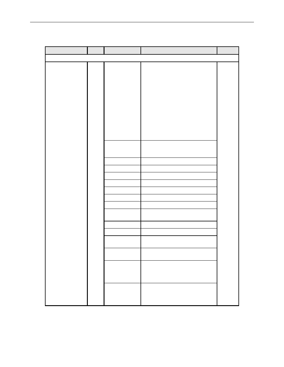
Table 3. RTAU Configuration Fields, continued
FIELD
TYPE
OPTIONS
DESCRIPTION
DEFAULT
SIGNAL GENERATOR SETUP FIELDS, continued
Loop Code
Toggle
OVERVIEW: The Mode field must be set to a
SPLT option before the Loop Code field can be
configured. Loop codes will be transmitted until
the RTAU detects a change in the signal being
received. At that time, the pattern selected before
the loop code was set will be transmitted. For
example, when sending a Loop Up code, the
RTAU will restore the original pattern after it
receives the loop code it is transmitting, indicating
that the circuit is looped up. Note that the Loop
Code bits are displayed in the Loop Code bit field
as each code is selected. This is provided as a
convenience to the operator who may not know
the name chosen for the loop code but does know
the pattern.
NONE
NONE
Disables any active loop code selected for this
field. When NONE is selected, the Loop Code
field displays 16 dashes.
Line Loop Up
10000
Line Loop Down
100
4-Bit Loop Up
1100
4-Bit Loop Down
1110
5-Bit Loop Up
11000
5-Bit Loop Down
11100
ESF CSU Loop Up
0EFF (0000 1110 1111 1111)
ESF CSU Loop
Down
38FF (0011 1000 1111 1111)
ESF NI* Loop Up
12FF (0001 0010 1111 1111)
ESF NI* Loop Down
24FF (0010 0100 1111 1111)
ESF CSU Payload
Loop Up
14FF (0001 0100 1111 1111)
ESF CSU Payload
Loop Down
32FF (0011 0010 1111 1111)
User Loop Up
(toggle and input)
Enter a 16-value expression using only 1’s, 0’s,
or “-”. The bits can be entered by typing a
string of 0’s or 1’s in the bit field located to the
right of the designated entry.
User Loop Down
Enter a 16-value expression using only 1’s, 0’s,
or “-”. The bits can be entered by typing a
string of 0’s or 1’s in the bit field located to the
right of the designated entry.
*Note: “NI” means Network Interface device.
(continued)