Perma pure llc, Od tubing is recommended – Perma Pure Mini-GASS User Manual
Page 9
9
Mini-GASS User Manual | Original Instructions
PERMA PURE LLC
Mini-GASS™ User’s Manual
Doc. #212: Revision: 00A
Page 9 of 32
Heatless air dryer (optional)
1. Connect oil-free compressed air line to port labeled “Purge Gas Inlet”
2. A ¼” FNPT bulkhead fitting on bottom of enclosure is the heatless dryer purge air
exhaust, see figure 3. Humid air can be vented to atmosphere or piped to a
remote location.
Purge air exhaust (optional)
To vent the purge gas exhaust to a remote location, connect a line to the ¼” FNPT fitting
labeled “Purge Exhaust Port”. This is suggested for gas samples that are toxic, flammable or
otherwise hazardous. In case of failure of seal integrity, the sample will be vented to the
remote location. For runs under 10 ft, ¼” OD tubing is acceptable. For runs 10-40 ft,
3/8
”
OD tubing is recommended.
TY PE A GC
O N
FUSE
5.0 A.
120 VAC
7 0 0
E
S
U
F
POWER
0
O FF
I
CA L 32 00
*
O N
1
S
E
2
F
U
S
U
F
E
G as Analysis Sam p ling System
M ini-G.A.S.S.
EXH AUST TEM PERATU RE
PURGE AIR
T M
Increase
Dec rease
PRESSURE ADJ.
Increase
Decrease
25
5
SUPPLY PRESSURE
FLOWMETER
0
30
p si
15
10
20
O FF
0. 8
0. 4
12 .8
6. 4
3. 2
1. 6
51 .2
25 .6
ON
128
8
32
16
64
2
1
4
O FF
TIMER SETTINGS
FILTER DRAIN
0. 1
0. 2
ON
TIM E DE LA Y
IN M INU TE S
S W ITCH E S IN
TIM E DE LA Y
FO R TO T AL
O N P O SI TIO N
0 .25
0.5
C O MB IN E
OFF
IN HO UR S
TIME D E LA Y
20
10
15
5
25
30
PURGE FLO WRATE
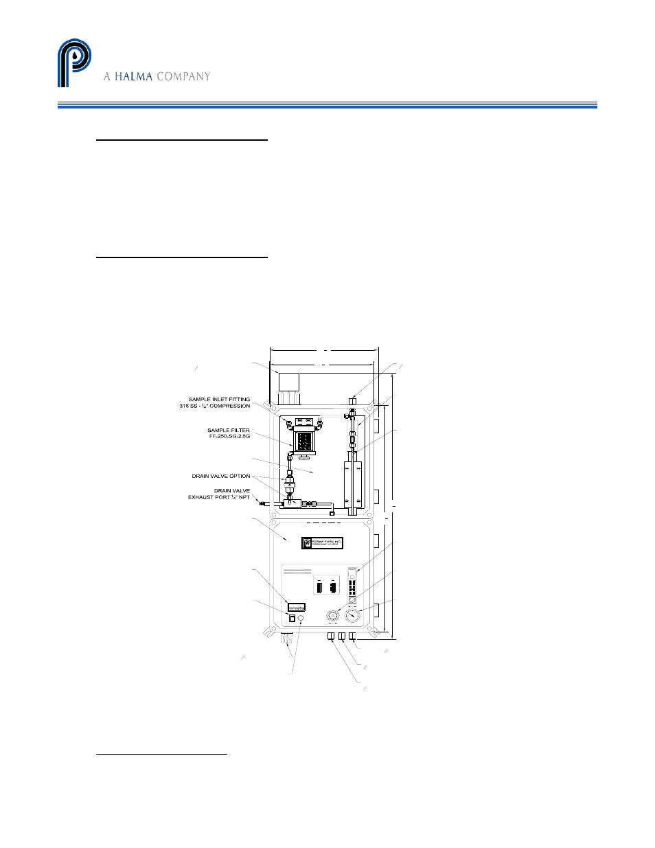
SAM PLE INLET
SEA LIN G FITTIN G FO R
1
1
2
" O .D . H E ATED LINE
H EATED BAC KPLATE
HEA TLESS D R YER OP TION
BELOW FR ON T PAN EL
D IGITAL ELEC TR ON IC
TEM PE RA TU RE C O N TR O LLER
PO W ER SW ITC H
PO W ER C O N N EC TION
1
2
" C O ND U IT H UB
110/220 VAC
FU SE
D RY SAM PLE OU TLET
316 S S -
1
4
" N PT FEM ALE
PUR G E AIR INLET
1
4
" N PT FEM ALE
H EATLES S D RYER
PUR G E AIR E XHAU ST
1
4
" N PT FEM ALE
PU R GE EXH AU ST POR T
1
4
" N PT FEM ALE
N AFIO N M EM BR ANE
D RYER
M OD EL PD -200T-24SA
PU R GE EXH AU ST
TEM PER ATU R E SEN SOR
M EM BR AN E D R YER
PU R GE AIR FLOW M ETER
FLOW M ETER SU PPLY
PR ESSU R E R EGU LATOR
FLOW M ETER SU PPLY
PR ESSU R E GAU GE
34
3
4
"
12
5
8
"
12
1
8
"
29
5
8
"
Figure 3 - Mini-GASS Sampling System
Filter drain (optional)
Connect the line from the eductor outlet to designated collection/exhaust basin containing
acid absorption media to prevent release of exhaust to surrounding. ¼” i.d. tubing can be