Perma pure llc – Perma Pure Mini-GASS User Manual
Page 31
31
Mini-GASS User Manual | Original Instructions
PERMA PURE LLC
Mini-GASS™ User’s Manual
Doc. #212: Revision: 00A
Page 31 of 32
APPENDIX F: Safety Interlock System
Control system safety interlock
The interlock system is present to provide an output signal that can be used internally to stop
sample flow via the optional internal sample pump. This system can also be used to provide an
external output to a PLC or other control/monitoring system so that the status of the Mini-GASS
can be monitored.
Two relays are used to perform this function:
• Low purge flow relay - A differential pressure switch across the purge air ports of the PD dryer
senses the flow of purge air and energizes this relay when flow is present. A minimum purge flow
rate of about 10 lpm is required. Below this flow, the alarm relay will de-energize.
• Low temperature relay – The CAL 3300 temperature controller has an alarm function that is used
to energize this relay when the system is operating at normal temperature. The actual point at
which a low temperature alarm is triggered is Set-point minus 5C. For instance, if the
temperature controller is set at 90C, the alarm relay will de-energize at 85C.
The interlock system is used in the Mini-GASS to control the optional internal sample pump by
simply supplying power to the sample pump motor via the alarm relays. Each of the relays is of a
DPDT or double pole double throw design. This just means that there are two sets of normally
open/normally closed (N.O./N.C.) contacts in each relay. One set of contacts is used internally and
one set of contacts is provided to allow connection to an external system.
• Refer the drawing MG-1228-04-12. Internally these relays are wired in series to supply power to
the sample pump. To accomplish this, switched line voltage (115,230VAC, Orange wire) is
supplied to the common (term. #5) connection of the low purge flow relay. From the normally
open (term. 3) connection of the low purge flow relay, a brown wire connects to the common
(term. #3) connection of the low temperature relay. From the normally open (term. #3)
connection of the low temperature relay, a gray wire connects to the sample pump. This allows
the pump to start only if both relays are energized.
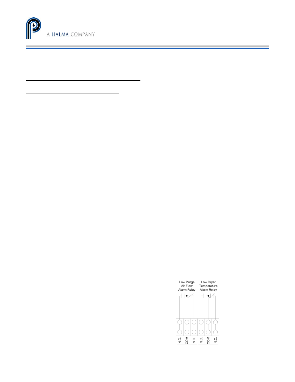
• Refer to Figure 20. For external connection, the second
set of contacts in each relay is “dry”. No power is
applied. This allows the user to determine the control
voltage that will be used. A typical use of the alarm
signal, as described above, is to control sample flow.
The actual use is left up to the customer.
Figure 20