Perma pure llc – Perma Pure Mini-GASS User Manual
Page 11
11
Mini-GASS User Manual | Original Instructions
PERMA PURE LLC
Mini-GASS™ User’s Manual
Doc. #212: Revision: 00A
Page 11 of 32
the equipment, within easy reach of the operator and shall be clearly marked as the
disconnecting device for the Mini-GASS.
Connect power supply line to terminal block located on the backplate of the control
enclosure inside the ½” conduit hub. (Refer to figure 5 for color coding). Connect the
system to an appropriate earth ground. Adhere to all electrical code requirements in effect
at the installation site. Connect power such that the protective earth conductor is the last to
take the strain.
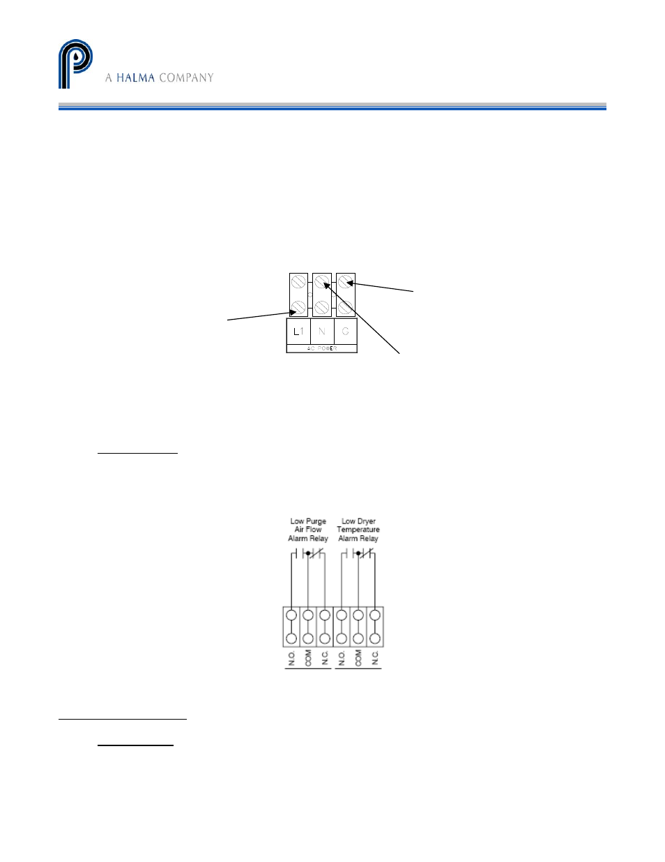
Figure 5 – Electrical Connections
Alarm Relays
The SIVS2 has a 6 pole terminal block that will allow for field wiring of alarm relays for
connection of external alarm equipment (refer to Figure 6). Relay contacts are rated at 250
VAC, 3A, resistive. See Appendix F for additional information.
Figure 6 – Alarm Relays
Start-up procedure
Setup Check
1. Check that electrical, sample purge drain and /or steam connections have been
made.
2. Turn on compressed or instrument air to system.
Blue – Connect neutral or Line L2 here
Green/yellow – Connect ground earth
here
Brown – Connect Line L1 here