Quick start guide wb5326 outdoor wireless bridge, Items included in kit, Hardware installation – Nitek WB5326 User Manual
Page 2
2
Quick Start Guide
WB5326 Outdoor Wireless Bridge
Items Included in Kit
(1) WB5326 RADIO
(1) PoE (48V, 1A)
(1) Mounting Hardware Accessories
(1) Quick Start Guide
(1) Product CD
Hardware Installation
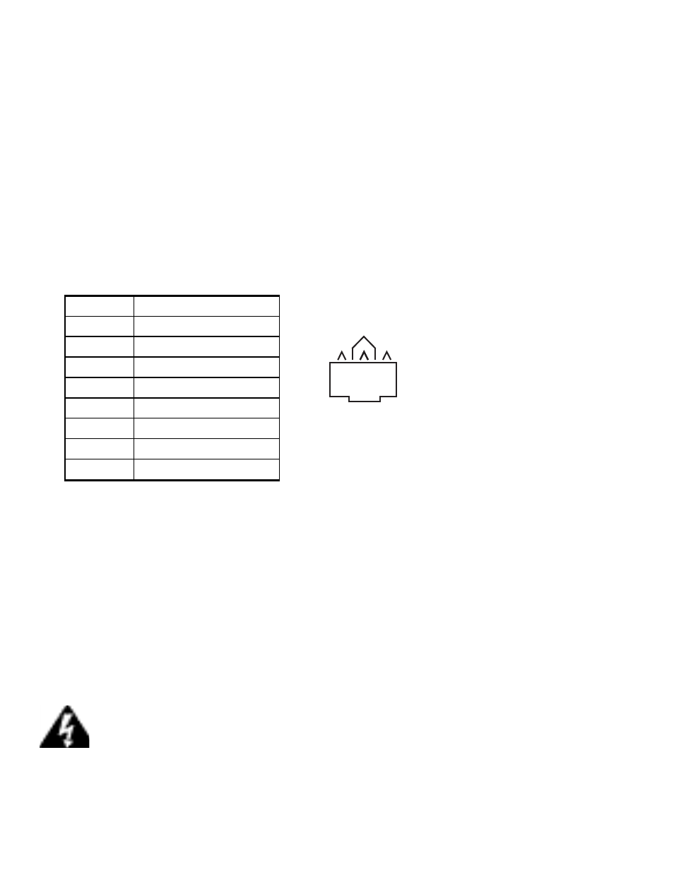
1. Put an Ethernet cable with RJ-45 connector through the water-tight joint. Make the RJ-45 connector as a 568B
wiring configuration:
2. Using the hardware provided mount the Bridge unit in position. Make sure that the Ethernet connection is
facing down. Keep in mind that the unit has a built-in antenna and must have line of sight between units. Refer
to separate mounting guide sheet for illustrations of hardware assembly.
3. Plug water-tight joint side of the Ethernet cable into the Bridge unit. Connect the other end of the cable to the
power injector supplied with the unit. Also connect a standard RJ-45 network cable for the power injector to a
hub or a terminal.
4. There is a ground connection on the Bridge unit located near the antenna port. The ground connection should
be connected to a proper earth ground point.
5. The antenna of the Bridge unit is behind the plastic face of the unit and must face the other Bridge unit. Make
sure you have line of site to the opposite unit and that they face each other.
Warning Do not mount Bridge unit near electric power lines, electric
lights or near strong electric power signals
6. Power the unit using the supplied PoE inserter.
12345678
568B
2
1
4
3
Terminal
Wire
1
Orange/White
2
Orange
3
Green/White
4
Blue
5
Blue/White
6
Green
7
Brown/White
8
Brown