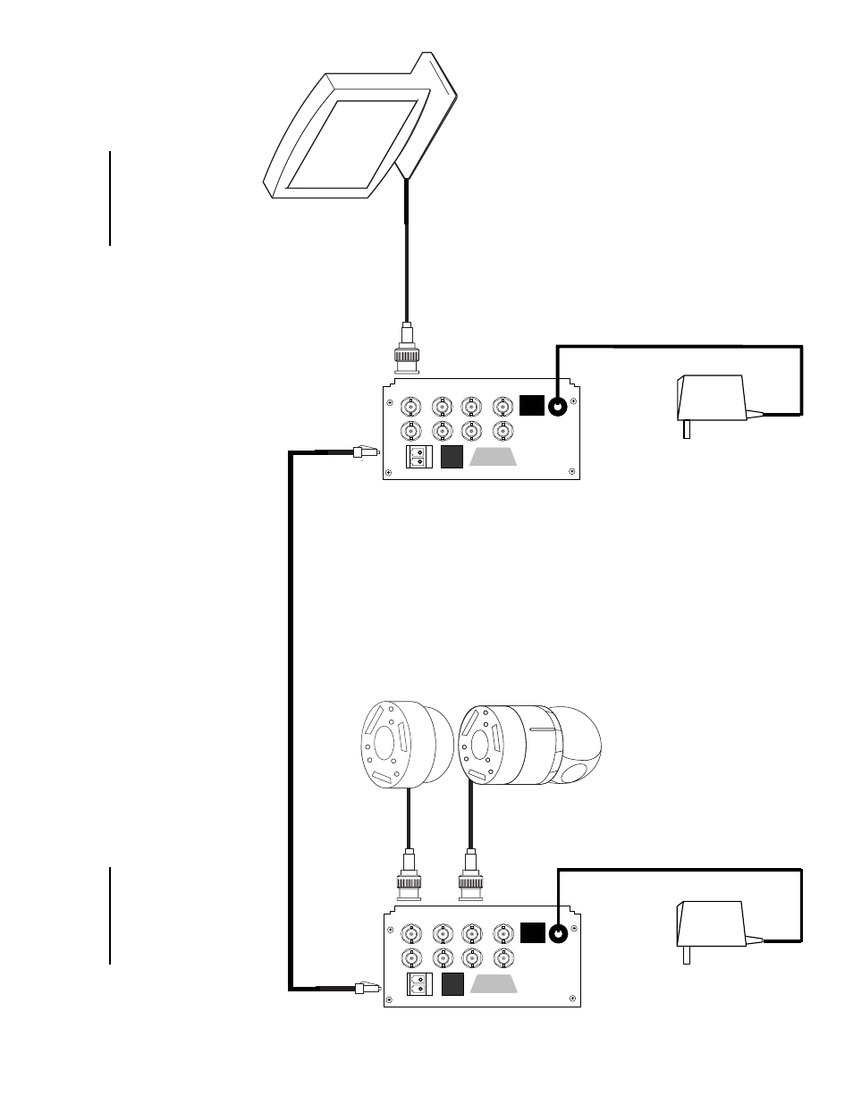
Ty pical inst allation diagram, Video in (1 or more) receiv er back panel – Nitek FRS581000R00 User Manual
Page 3
T
y
pical Inst
allation Diagram
15VDC
Class 2
Power Sup
p
ly
(Stand Alone)
Transmitter
Back Panel
CH1
CH2
CH3
CH4
CH5
CH6
CH7
CH8
PRI
M
AR
Y
TX
R
X
SECO
NDAR
Y
TX
R
X
ETHERNET
DATA
MANAGEMENT PORT
Video In
(1 or more)
Receiv
er
Back Panel
CH1
CH2
CH3
CH4
CH5
CH6
CH7
CH8
PRI
M
AR
Y
TX
R
X
SECO
NDAR
Y
TX
R
X
ETHERNET
DATA
MANAGEMENT PORT
Video Out
(1 or more)
15VDC
Class 2
Power Sup
p
ly
(Stand Alone)
Single-Mode Fiber with LC Connectors
Connect T
X
output on transmitter to RX
input of receiver
Rack Mou
n
t
1) Inser
t u
n
it into
fiber card rack and se-
cure mounting screws.
2) Make e
lectrical and fiber connections
as illustrated below
.
Stand Alone
1) Mount unit securely to the wall using
supplied mounting bracket.
2) Make electrical and fiber connections
as illustrated below
.