Installation, System components – Nitek TS510M User Manual
Page 2
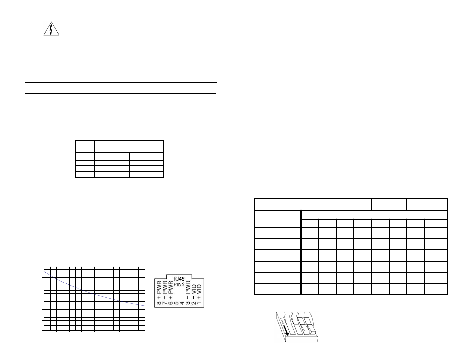
Unm arked Positions are O ff
Video
Level Gain
Video
Peaking
Distance
Switch Position
1
2
3
4
5
6
7
8
<100-400 ft.
(30-121 m)
400-700 ft.
(121-213 m )
ON
700-900 ft.
(213-274 m )
ON
ON
ON
900-1,100 ft.
(274-335 m )
ON
ON
ON
1,100-1,300 ft.
(335-396 m )
ON
ON
ON
ON
>1,300 ft.
(396 m)
ON
ON
ON
ON
ON
1)
Check the twisted pair connections for continuity. This is best
done by shorting the pair of wires at one end and use an ohm meter
to check the resistance at the other end. The chart below will give
you the length of your wires for a measured resistance. Use a
multimeter to make sure there is no voltage on the line.
The TS510M is designed to power a low wattage stationary camera.
The unit is designed to work with standard 4 pair network cable. It
will provide power from the receiver unit to the camera end. The
chart below shows the maxium recommeneded operation distance
for cameras on 24AWG wire. For distances greater then the chart
a camera may be powered from a sperate supply of its own. The
TS510 M is not recommended for distances greater then 1,500 feet.
Installation
WIRE
GAGE
DISTANCE IN FEET
(METERS)
500 (152)
1,000 (304)
22
16
32
24
26
51
26
41
82
Reduce risk of fire or electrical shock do not
expose this product to rain or moisture.
Sample
Switches 1 and 2 are in “OFF” position
Switches 3 and 4 are in “ON” position
System Components
1 TR510M Active Receiver Unit
1 VB43ATF Transceiver Unit
2) At the camera, connect video to the VB43ATF via attached
BNC connector.
3)
Connect power from the VB34ATF screwless terminals to the
camera using the enclosed twisted pair wired.
4)
Plug in Category 3 or better cabling connecting VB43ATF to the
TR510M
5)
Using a power supply connect power to the screw terminals of the
TR510M active receive. The unit can be powered using 12 to 24 volts
of AC or DC current. There is no polarity to the power connection.
6)
Connect video from the TR510M to the monitor or DVR using a coax
jump cable.
7)
DIP switches are provided so that the unit can be adjusted for
best picture. The following settings are factory recommended for
normal conditions. For added sharpness adjust switches 7 and 8.
For more gain adjust 5 and 6. Switches 1, 2 and 3, 4 must be
operated in pairs.
0
200
400
600
800
1000
1200
4
4.5
5
5.5
6
6.5
7
7.5
8
Operating Distance Chart
Camera wattage
Dis
tyanc
e i
n F
eet