Nm-modlamp (scm2 scm3), Nm-modlamp, Installation procedures – NetMedia MODLAMP-DI User Manual
Page 2: Cable channel 125, Uhf channel 25
NM-MODLAMP
MAN-MODLAMP REV1002A
NM-MODLAMP (SCM2 SCM3)
NetMedia, Inc., 10940 N. Stallard Place, Tucson, Arizona 85737 (520) 544-4567 Fax: (520) 544-0800 Email: [email protected] www.netmedia.com
DO NOT CUT OR SPLICE THE CAMERA’S CABLE. MODIFYING THE UNIT IN ANY WAY WILL VOID THE WARRANTY.
Installation Procedures:
1. Remove the Housing Cap from the camera assembly and pull the Camera Bracket out to set the channel with the
switches as shown in Figure 1. Choose an unused channel that matches the tuning mode of the televisions. With
antenna tuning, choose a UHF channel from 14-69. With cable tuning, choose a CABLE channel from 70-94 or 100-125.
There must be at least one blank channel on either side of the modulated channel to separate it from any other broad-
cast, cable, or modulated source. When combining with cable service, be aware that digital data typically interferes with
channels 80-117, even when not subscribed to digital services. Channels 120-125 often work without any filtering.
2. Ensure that the camera is grounded with the ground strap as shown in the FCC Information. Connect a coax cable from
the camera’s F connector to the “MOD” side of the Power Injector. Connect the “TV” side of the Power Injector to the
grounded coax from a television or distribution system. Connect the 12V DC 300mA power supply to an AC outlet and
the Power Injector. The camera picture is now available on the programmed TV channel.
3. Mount the base to the junction box (not included) and adjust the camera assembly for proper viewing. When satisfied,
secure all adjustment points.
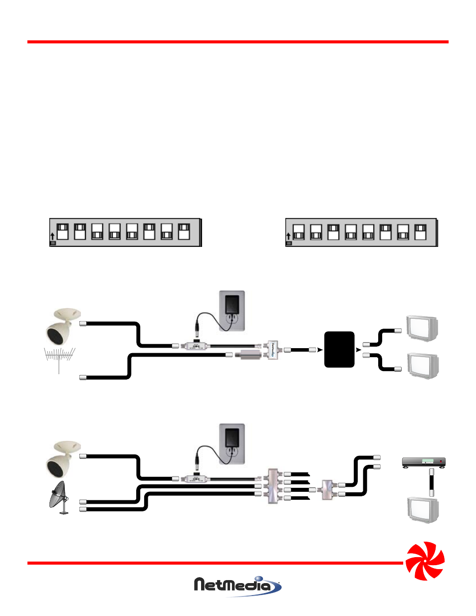
Figure 1 - Setting the modulated channel with the switches. Valid channels are UHF 14-69, CABLE 70-94, 100-125.
80 40 20 10 8 4 2 1
ON
OFF
CABLE Channel 125
Add the numbers
printed on the
circuit board.
80 40 20 10 8 4 2 1
ON
OFF
UHF Channel 25
Figure 3 - Connecting the camera to a satellite system and distributing to multiple televisions.
Figure 2 - Connecting the camera to an antenna or cable service and distributing to multiple televisions.
Dual LNB
Satellite
Satellite
Multiswitch
w/Ant input
Satellite
Diplexer
Television
Satellite Receiver
Sat In
Ant In
Power Injector
Camera
Main cable or
Antenna
Television
Television
Power Injector
Distribution
Panel
or Splitter
Camera
Optional Ch. 70-80 Filter (NM-CNF7080)
when there are no clear cable channels.
Splitter/
Combiner