2 wiring diagram, Page 17 – DoorKing 1819 Information Phone User Manual
Page 17
1819-065-B-4-07
2.2
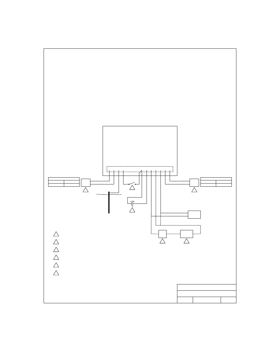
Wiring Diagram
DOORKING, INC., INGLEWOOD, CA 90301
Title:
Date:
Rev.
Dwg. No.
PWR
INPUT
1
Phone
Line
5
6
4
MAIN TERMINAL
Strike /
Mag Lck
Gate
Operator
Lock
Pwr
3
2
1819 Field Wire Diagram - 1862 Control Board
4/07
A
M1819-065-1
Phone Line Wiring Max Distance
800 Feet
1600 Feet
24 AWG
22 AWG
Power Wiring Max Distance
100 Feet
200 Feet
18 AWG
16 AWG
16 Volt, 20 VA UL Listed power transformer.
1
2
Power for door strikes or magnetic lock is not provided by the
system. It must be provided by an external power supply.
3
Electric strikes are wired to Normally Open (N.O.) contacts; magnetic
locks are wired to the Normally Closed (N.C.) contacts.
4
Optional 12 Volt gel cell for backup power.
5
Dedicated Central Office (C.O.) phone line - touch tone, loop start.
6
A switch closure across terminals 4 & 8 will activate relay 1 for its programmed
strike time. This is where the postal switch is prewired.
All wiring to be performed in accordance with National Electric Code.
10 11 12 13 14
1
9
8
7
6
5
4
3
2
1862-010
Circuit Board
1819 Field Wire Diagram - 1862-010 Control Board
Earth
Ground
Page
17