2 triggering stimulation (trigger in) – Multichannel Systems STG1000 Manual User Manual
Page 50
Stimulus Generator 1000 Series User Manual
44
10.2 Triggering Stimulation (Trigger In)
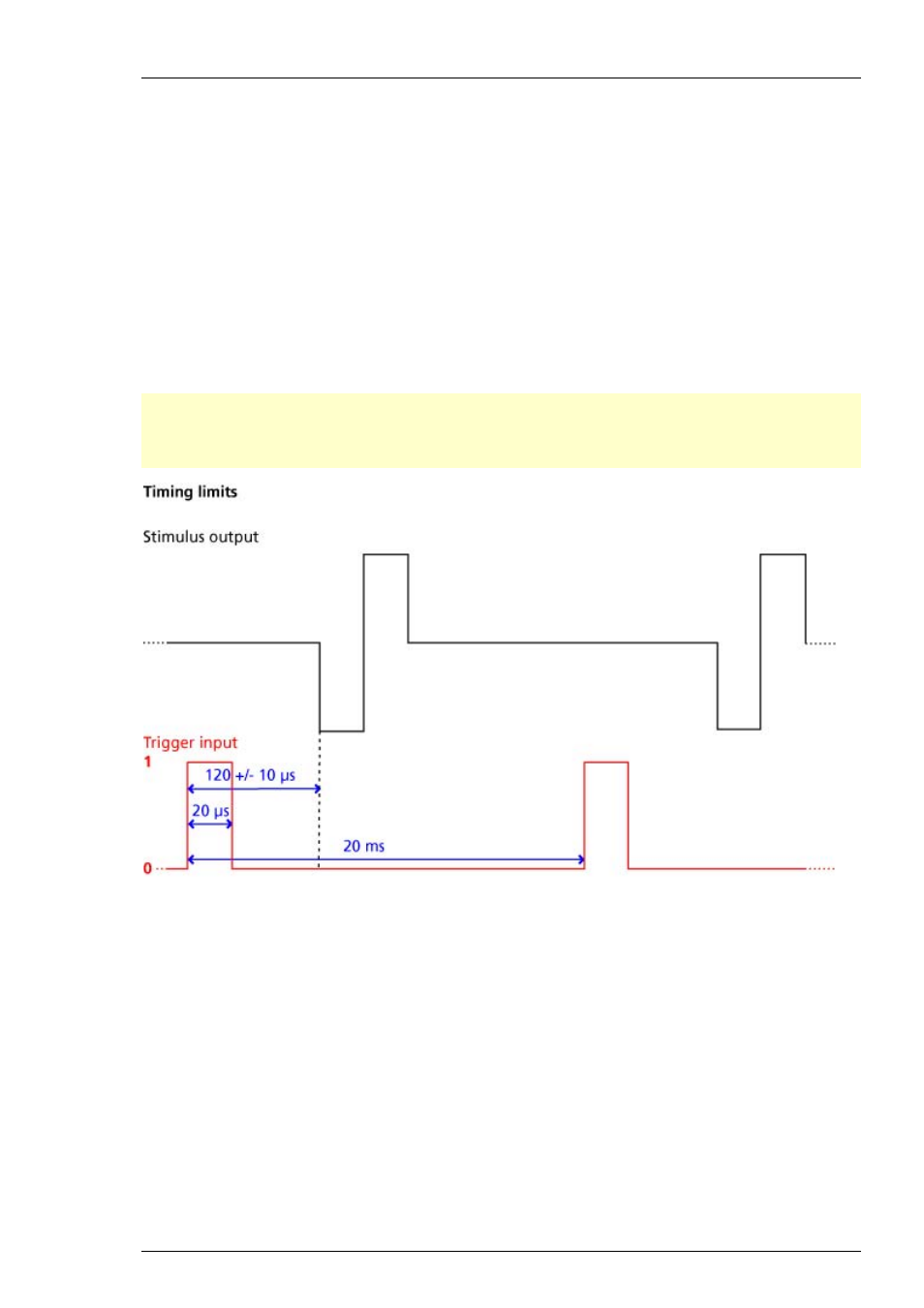
The external trigger input has to be a TTL signal of at least 20 μs length. TTL pulses shorter than
that may not be recognized by the stimulus generator.
A TTL pulse is defined as a digital signal for communication between two devices. A voltage
between 0 V and 0.8 V is considered as a logical state of 0 (LOW), and a voltage between 2 V and
5 V means a 1 (HIGH). It is the same kind of signal as the output signal of the Sync Out output of
the STG.
The rising edge of the HIGH trigger input starts and stops the STG. The time lag between the
rising edge of the TTL input and the stimulus output is 120 +/ 10 μs. The minimum distance
between two trigger inputs is 20 ms, resulting in a maximum trigger frequency of 50 Hz. If a
higher frequency is used, the stimulus generator is likely to miss trigger inputs. See the illustration
below for more details on the timing. Please note that the digital Sync Out output is about 15
μs faster than the analog outputs. See Digital Output Signal (Sync Out) for more information.
Important: Please note that the
timing
and the
amplitude
of the analog output pulses may not
be accurate for very small amplitudes (
below 200 mV
or
below 100 μA
) due to the intrinsic
properties of the electronic parts of the stimulus generator. Please check the output signals with
an oscilloscope if you use small amplitudes in your stimulus protocol.
Custom switch for "remote-controlling" of the STG
You can connect any device that produces TTL outputs to the Trigger In connector of the STG, for
example a switch. For example, you can use a trigger for remote controlling the STG if it is not
within reach during an experiment. It is also possible to set up advanced experiments where
stimulation depends on preceding activities of the studied object.
The following picture shows a suggested circuit diagram for a switch used for remote controlling.
The resistor and capacitor work as a low-pass filter on the TTL signal and are necessary to reduce
ringing of the signal.