Detectors and input signals, 80c31 multi-processor system, Internal lc-display: 2 x 16 characters – Mirion Technologies DSK_DMK 250 User Manual
Page 2: Calibration of detector signal to power density, Dsk 250: fl ux density for each detector position, Dmk 250, Average fl ux, Flow related fl ux, Mechanical vibrations: < 5 g, 5 hz
Since norms, specifi cations and designs are subject to occasional change, please ask for confi rmation of the information given in this publication.
Mirion Technologies (MGPI) SA
Route d’Eyguières
FR-13113 Lamanon
France
T +33 (0) 4 90 59 59 59
F +33 (0) 4 90 59 55 18
Mirion Technologies (MGPI) Inc
5000 Highlands Parkway
Suite 150
Smyrna, GA 30082
USA
T +1 770 432 2744
F +1 770 432 9179
Mirion Technologies (MGPI H&B) GmbH
Landsberger Strasse 328a
DE-80687 Munich
Germany
T +49 (0) 89515 13-0
F +49 (0) 89515 13 169
Mirion Commercial (Beijing) Co., Ltd.
Shanghai Jiangchang Commercial Branch
Room 801, 78 Jiangchang SanLu
Zhabei District, Shanghai 200436
PR of China
T +86 21 6180 6920
F +86 21 6180 6924
DSK/DMK 250
Neutron Flux Instrumentation
www.mirion.com
144969EN-C
DETECTORS AND INPUT SIGNALS
●
Miniature in-core fi ssion chambers, e.g. WL 23630
(IST), MNK/MBK 61 (Siemens-Areva)
●
Cable to the DSK 250: coaxial cable, no limitation of
length
●
Detector supply: -50 ... -200 V individually
adjustable for each detector
●
Range of detector current: 32 ... 4000 μA adjustable to
full scale
●
Input signal for coolant fl ow: 0/4 ... 20mA
DIGITAL SIGNAL PROCESSING
●
80C31 multi-processor system
●
Program memory: EPROM
●
Parameter memory: CMOS-RAM with integrated
Li-battery
●
Data interface: RS232 and/or RS485
●
Internal LC-display: 2 x 16 characters
●
DSK 250 processes four detector signals in four
individual signal paths:
○
Calibration of detector signal to power density
○
Alarm threshold for local density in relation to coolant
fl ow
●
DMK 250 accumulates up to 64 detector lines (16
DSK 250):
○
Calculation and calibration of average reactor power
○
Calculation of fl ow related fl ux and margin to scram
○
Flux oscillation monitoring combining transient sup-
pression and fast response
OUTPUT SIGNALS
●
DSK 250: fl ux density for each detector position
●
DMK 250:
○
Average fl ux
○
Flow related fl ux
○
Magnitude of fl ux oscillations calibrated to reactor
power, e.g. 0 ... 125 %Pn
●
Analog outputs: 0/4 ... 20mA/600 Ω, insulated
●
Binary outputs: insulated relay change overs,
60V/0.5A or 125V/1A
OTHER CHARACTERISTICS
●
DC power supply: 18 ... 33 VDC, approx. 1.6A at 24 V
(each DSK and DMK)
●
Optional: AC power supply: 230 VAC or 115 VAC
+10%/-15%, approx. 40 VA
●
Operating temperature: 0 ... 70°C (32 ... 158°F) for the
main electronics
●
Mechanical vibrations: < 5 g, 5 ... 100 Hz
●
19” modular system according to IEC 60297
●
Rack size (W×H×D): 483 mm × 133 mm × 280 mm
(19 in x 5.2 in x 11 in)
●
Plug-in boards: 100 mm × 160 mm (3.9 in x 6.3 in)
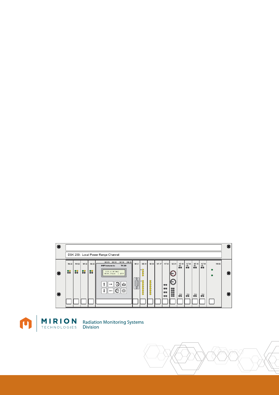
DSK 250
front view