Wiring & conn, Wiring & connections – Micromod MOD: 1726F Output holder for MOD 30ML User Manual
Page 9
Using The Output Holder With MOD 30ML
Output Holder Purpose
5
WIRING & CONNECTIONS
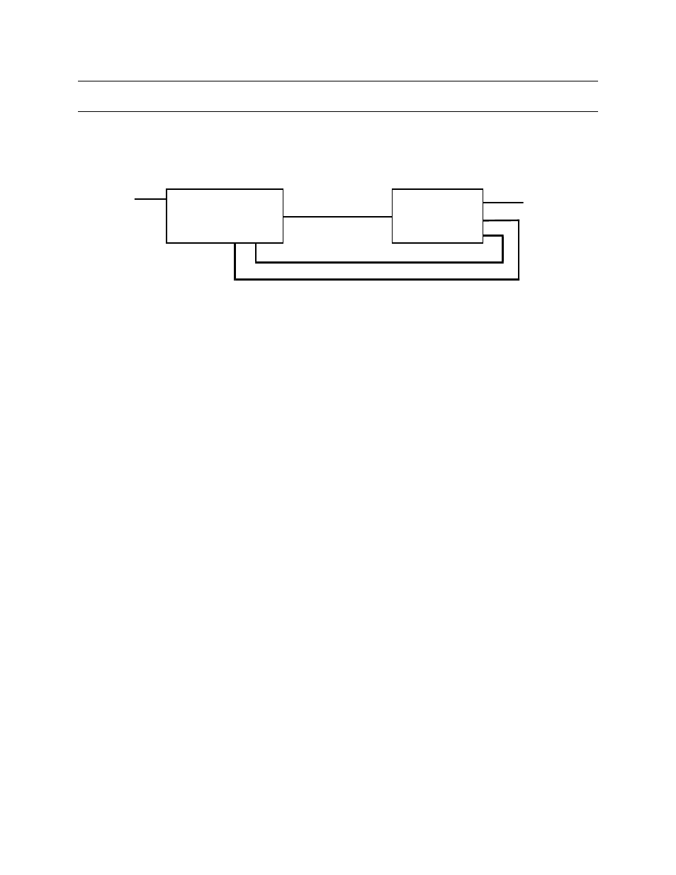
Figure 2 provides a generic reference as to the signal paths between the controller and
the 1726F Output Holder card. Table 1 provides a complete output holder wire color and
signal listing as viewed from the 1751FZ output holder cable. This is required to provide
detailed wire connection for multiple output holder applications to a single controller.
Figure 2. Generic Output Holder Connection Diagram
For the Sense and Return signals to be received by the MOD 30ML Controller two inputs
are required. The input types are:
•
non 2-wire current input
•
digital input (2006AZ)
The current input is used for the Return signal and is configured for 1-5 milliamps. The
2006AZ digital input module is used to bring in the Sense signal.
The exact wire connections for a particular MOD 30ML Controller output holder
application depend on how many outputs are being held and where the Sense and Return
I/O points for each loop are located on the controller. If Built In Analog Input #2 is not
being used for control it may be set up for 1-5 milliamps non 2-wire and used to bring in
the Return signal. In all cases the Sense signal will require the installation of a 2006AZ
digital input module.
To Process
1726F
Output Holder
MOD 30ML
Controller
I Return
O. H. Sense
4-20 mA
Process Input
4-20 mA
Controllers
Output