Micromod MOD: 1726F Output holder for MOD 30ML User Manual
Page 8
Using The Output Holder With MOD 30ML
Output Holder Purpose
4
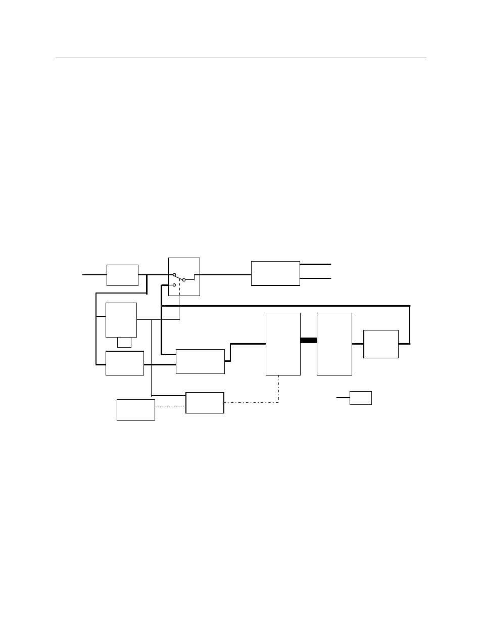
value is being sent to the field the Clock Control permits the clock pulses to reach the D/A
Converter causing it to float with the controllers output value.
The Up/Down Counter counts clock pulses and either increments or decrements the
count value at its parallel output.
The D/A Converter receives the counters value and converts it to a 1-5 Vdc signal. This
value is in turn sent to the Analog MUX circuit through the Output Conditioning circuit.
The V/I Converter circuit converts the 1-5 Vdc signal to 4-20 milliamp output and 1-5
milliamp Return signals to be used by the field and controller respectively.
The Return line is sent back to the controller and is used to synchronize its output to that
of the output holder in order to cause bumpless transfer when a controller is first brought
on line.
The Sense line is generated on the output holder card and is nothing more than a dc
common. This signal is sent back to the controller and is used to determine if an output
holder card is present.
Figure 1. Basic Functional Block Diagram
I/V
Converter
Analog
MUX
V/I
Converter
Up/Down
Control
Clock
Control
Up/Down
Counter
D/A
Converter
Input
Monitor
Input
Conditioner
Output
Conditioning
75 MHz
Clock
4-20 mA
1-5mA
4-20mA
Return
Output
V out
-8%
Enable/Disable
Clk
Bit 0
Bit 10
Hold Value
Run/Hold
Sense
Gnd