Using modbus modules – Micromod MOD: MODBUS RTU Communications Guide User Manual
Page 14
MODBUS RTU
COMUNICATIONS GUIDE
10
USING MODBUS MODULES:
MODULE LOCATION
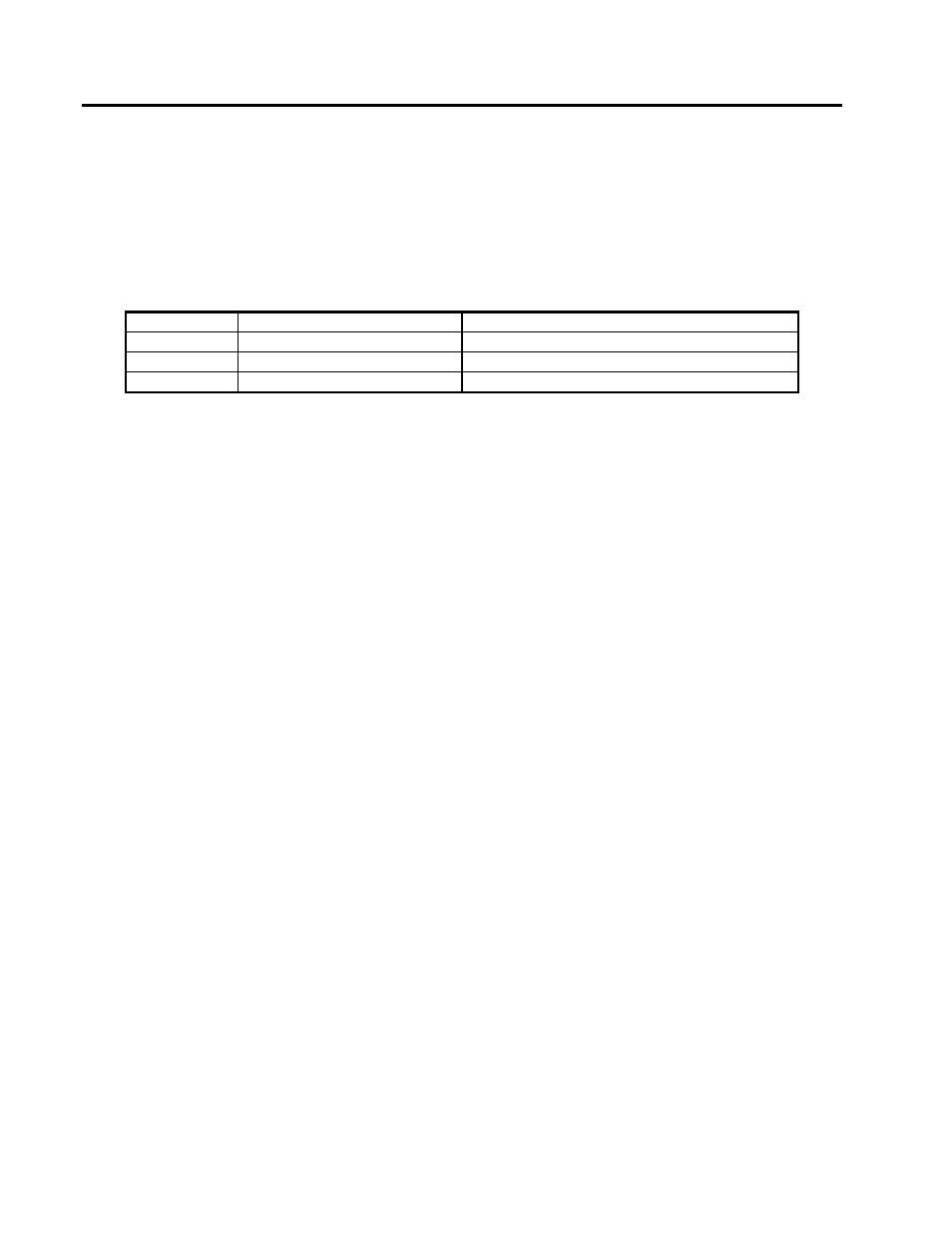
The sockets in which the module is installed determines its Port number
Table 4. MOD30ML and Modcell MLP Port Numbers
Port Number
MOD30ML
Modcell MLP
1
Built-In, Slots 9-10 or 10
Slots 31-32 or 32
2
Slots 7-8 or 8
Slots 29, 28-28, 30 or 29-30
3
not available
Slots 25-26, 26, 26-27, 27, 27-28 or 28
THE RS-485’S TERM (MASTER/SLAVE) SWITCH
•
The master is responsible for stabilizing the bus
•
In the YES position the module provides this master function by pulling the comm+ line high and
the comm- line low, each through 560
Ω
resistors
•
Some PC cards have these resistors built in, generally only on the receiver. This works fine in 4-
wire mode if the transmitter does not tri-state, or in 2-wire mode. 4- wire mode, with a tri-stating
transceiver, may require a module to have its switch in the master position, even if its not acting
as the master.
THE COM DEFAULTS SWITCH
•
If the MOD30 ML or Modcell MLP configuration is unknown, setting this switch to th eYES position
will allow communications with the unit at 9600 baud, no parity, 8 data bits and 1 stop bit. After
downloading the desired parameters, remove power, COM DEFAULTS switch to NO and power
up.
THE HIGH AND LOW SWITCHES
•
Set the MODBUS Address
•
The High switch sets the first hexadecimal digit of the address, and the Low switch sets the
second. For example, a switch setting of 13 hex represents a decimal address of 19.
The 2-wire RS-485 module has no switches. It must be configured by the Application Builder software, to
change the factory defaults. The factory defaults are 9600 baud, no parity, 8 data bits, one stop bit and a
MODBUS address of one. Do not connect an unconfigured module to a network if there is another device on
the network with address one.