Electrical installation - wiring, Frequency single phase, Current sinking* wiring (models 29x-6xx) – Max Machinery G240 Gear Flow Meter User Manual
Page 13: Frequency quadrature, Wiring frequency, Wiring diagram, Frequency single phase wiring
Max Machinery, Inc. G Series User Manual © Copyright 2013
Rev. 001Q4
Frequency
Single Phase
Wiring
PCA label
Mating Cable
Wire Color
Turck
Pin #
Case Ground
Case
Blue
3
Common
Com
Black
4
Power 5-26 Vdc
V+
Brown
1
Pulse Output
Ph A
White
2
N/A
NC
Grey
5
Frequency
Single Phase
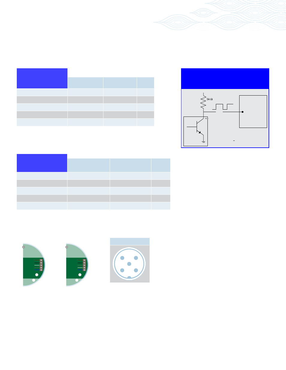
* A current sinking device produces an output pulse which is the opposite of a sourcing device.
A positive DC voltage must be applied to the wire running between PhA and your PLC. When the
output is triggered, this voltage will be grounded to zero volts. Note: use a 5k ohms resistor to limit
the current flow in the signal line.
Current Sinking* Wiring
(models 29X-6XX)
PLC
Digital
Input
V+
V+
Out
0V
Transmitter
Turck Pin #2
PCA label
Mating Cable
Wire Color
Turck
Pin #
Case Ground
Case
Blue
3
Common
Com
Black
4
Power 5-26 Vdc
V+
Brown
1
Output Phase A
Ph A
White
2
Output Phase B
Ph B
Grey
5
Frequency
Quadrature
Electrical Installation - Wiring
Wiring FREQUENCY
The electrical connector versions are pre-wired inside the transmitter and ready to accept a mating cable (available from
the factory). The liquid-tight, NPT models need to be wired during installation as shown in the table below:
Turck Connector
2
1
4
5
3
(Brown)
(Black)
(Grey)
(White)
(Blue)
Wiring Diagram
(Brown)
(Black)
(Grey)
(White)
(Blue)
Freq
V+
Com
PhA
PhB
Case
Analog
V+
Com
Sig
Ret
Case
Model 295/296
*
*
*Serial interface receptacle.