Mallory Ignition ACCEL SELF LEARNING MODULE SLMхх User Manual
Self learning module installation instructions, For harley-davidson, Throttle by wire touring models – part no. slm06
1
ACCEL
www.accel-motorcycle.com
SELF LEARNING MODULE INSTALLATION INSTRUCTIONS
For Harley-Davidson
®
Throttle by Wire Touring Models – Part No. SLM06
FORM SLMINST06 10/10
STEP 1 - BATTERY CONNECTION
Locate the battery and disconnect the negative battery cable. Mount the
SLM module under the seat with the harness directed toward the front of
the bike. The SLM module can be mounted with Velcro or zip ties
(not included).
STEP 2 - THROTTLE POSITION SENSOR (TPS):
Remove the air cleaner assembly and unplug the TPS sensor
connector at the TPS sensor. The harness includes (2) TPS connectors
which should be routed under the gas tank into the factory wire loom
to the TPS sensor. The TPS sensor is located on the left side of the
throttle body. Plug the (2) TPS connectors from the module in between
the TPS sensor and to the factory TPS connector.
STEP 3 - O2 SENSOR:
Remove the right side cover to access the 02 sensor connectors. There is
a black plug for the front 02 sensor and a grey plug for the rear 02 sensor.
Route the SLM 02 sensor connectors into the space behind the right side
cover. Unplug the black 02 sensor connector from the factory harness and
plug the (2) SLM black 02 sensor connectors in between. Repeat the
process for the grey 02 connector.
STEP 4 - CRANK POSITION SENSOR
The crank position sensor is located at the lower front crank case area
behind the front motor mount. Route the SLM module’s (2) crank position
sensor connectors along the motorcycle’s lower right side frame along
with the main harness loom. Unplug the crank position sensor from the
factory harness and plug the (2) SLM crank position sensor connectors
in between.
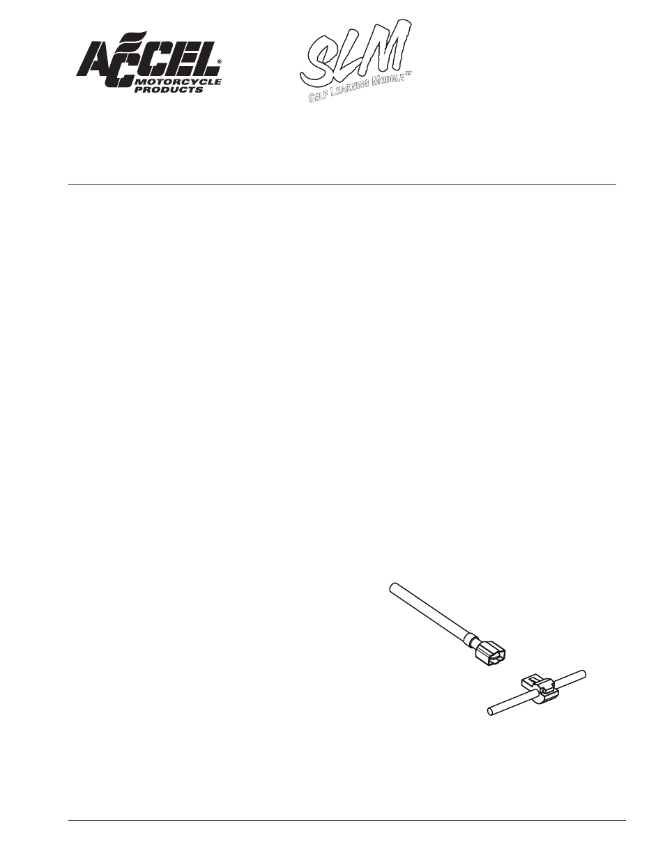
STEP 5 - POWER SOURCE:
The SLM module requires two power sources on the Throttle By Wire
applications. Connect the red/white wire with eyelet from the SLM to
the positive side of the battery. Connect the red wire from the SLM to
the keyed on 12 volt power source located at the Data-Link connector
pin #4 (grey wire). The Data-Link connector is located under the left
side cover. Connections can be made with the supplied t-tap and
blade terminal but we recommend soldering and heat shrinking this
connection.
STEP 6 - GROUND SOURCE:
All models with factory 02 sensors do not require a ground.
Reconnect the negative battery cable to complete the installation.
FUNCTIONS AND OPERATION OF THE SLM MODULE
The LED is located at the upper right corner on the front of the module.
The Led will blink red with the key on. The LED will turn Green after the
motorcycle has been running for approximately 90 seconds.
Limited Camshaft Modifications
The SLM module will facilitate for the installation of, exhaust
systems, air cleaners/intake systems, including limited camshaft
modifications. The camshafts are limited to "most bolt in camshafts",
where the installation does not exceed the maximum lift listed below:
• 0.520” lift for a 88ci to103ci motors
• 0.580” lift for 96ci to 110ci motors, w/no changes to the factory valve
or rocker arm configurations
The SLM module may support limited camshaft installations, when no
other changes are made to the motor, this would apply to an
88ci to a 110ci camshaft upgrade only. When installing camshafts over
0.600” of lift which also includes additional engine modifications, there
would be a need to have the engine tune with an after market tuner.
After the motor has been tuned in to accept the new camshafts and
additional engine modifications, the SLM module may be installed to
fine/tune the closed/loop system.
READ ALL THE DIRECTIONS CAREFULLY BEFORE STARTING THIS INSTALLATION. DO NOT APPLY FORCE WHEN INSTALLING THE
SENSOR CONNECTORS TO THE SENSORS. THIS WILL RESULT IN BENDING THE ALIGNMENT OF THE TERMINAL PINS, LOCATED IN
THE CONNECTORS AND SENSORS. USE THE MODEL SPECIFIC DIAGRAMS TO DETERMINE WIRE FUNCTION. IT MAY BE NECESSARY
TO REFER TO A FACTORY SERVICE MANUAL TO PROPERLY LOCATE THE APPROPRIATE SENSORS TO COMPLETE THIS INSTALLATION.
Blade Terminal
T-Tap
Power Wire