Coil, Figure 5, Wiring with loom resistance wire – Mallory Ignition Mallory MAGNETIC BREAKERLESS IGNITION MODULE 609 User Manual
Page 4
4
MALLORY IS A DIVISION OF THE MR. GASKET PERFORMANCE GROUP
550 MALLORY WAY, CARSON CITY, NV 89701
(775) 882-6600
FAX (775) 887-4326
www.mrgasket.com
FORM 1356
REV. C (2/00)
MADE IN U.S.A.
PRINTED IN U.S.A.
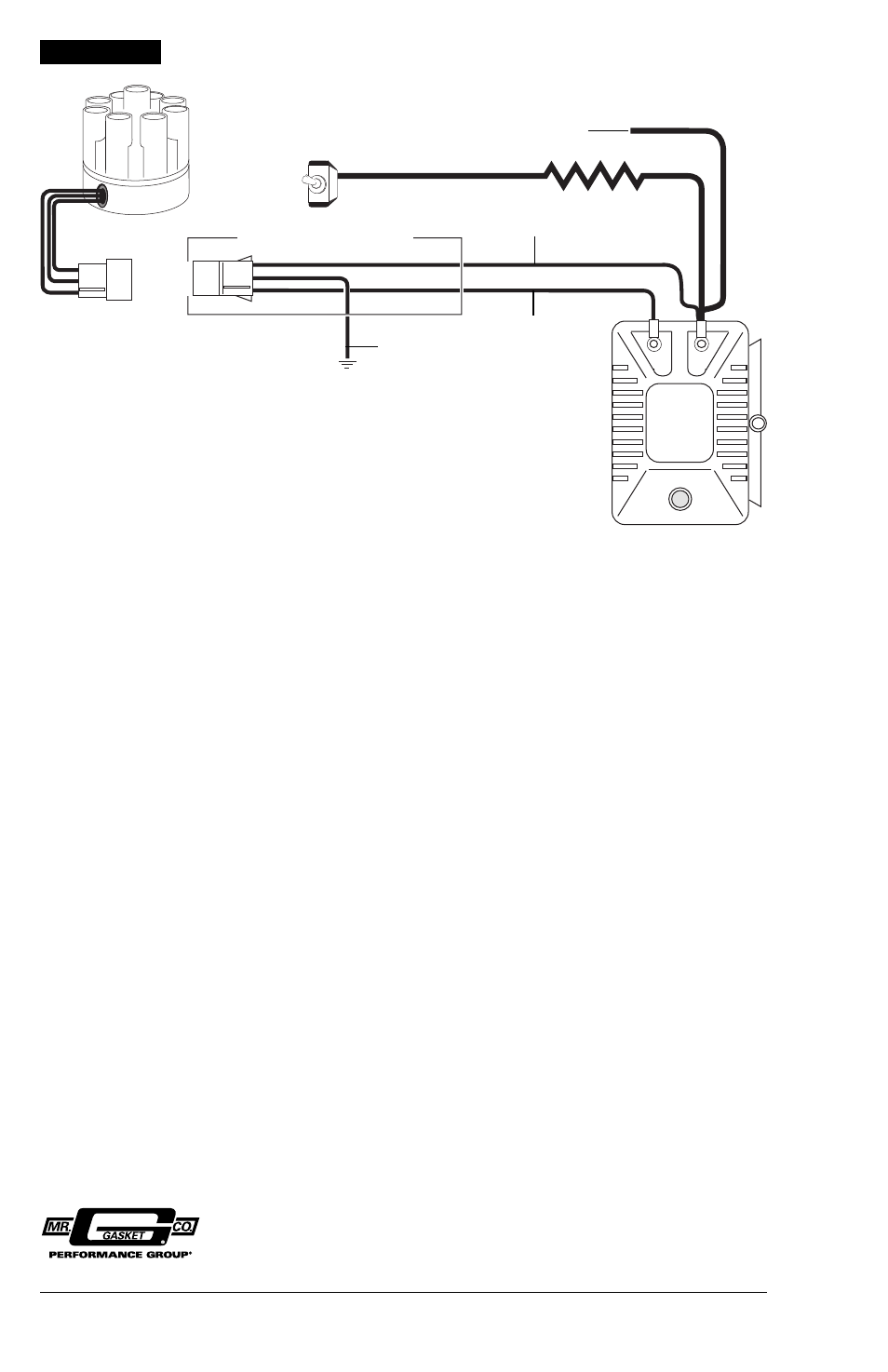
FIGURE 5
COIL
–
+
ALL OTHER WIRES ORIGINALLY CONNECTED
TO THE COIL (+) TERMINAL
12V/IGNITION
SWITCH
DISTRIBUTOR WIRE HARNESS
PART NO. 29349
IGNITION MODULE
FEMALE CONNECTOR
ENGINE
GROUND
BROWN
GREEN
RED
LOOM RESISTANCE WIRE
NOTE: The purpose of loom resistance wire between
the ignition switch (12V) and the ignition coil positive
terminal is to restrict current flow through the ignition
coil. Failure to use an ignition ballast resistor will
eventually destroy the Ignition Module.
EXCEPTION: If your vehicle is equipped with a HYFIRE
®
Electronic Ignition Control or similar aftermarket ignition
control, use the wiring procedures stated in the
instructions included with the ignition control.
To prevent false triggering and possible premature
ignition failure, you must use suppression type (carbon
core, spiral core, or radio suppression core) spark plug
wire.
DO NOT USE SOLID CORE (COPPER CORE OR
STAINLESS STEEL CORE) SPARK PLUG WIRE WITH
ANY ELECTRONIC IGNITION SYSTEM.
WIRING WITH LOOM RESISTANCE WIRE