Coil, Equipped with external ballast resistor – Mallory Ignition Mallory E-SPARK BREAKERLESS CONVERSION KIT 61010M_61011M User Manual
Page 5
5
MALLORY TECHNICAL SUPPORT
(775) 882-6600
www.malloryracing.com
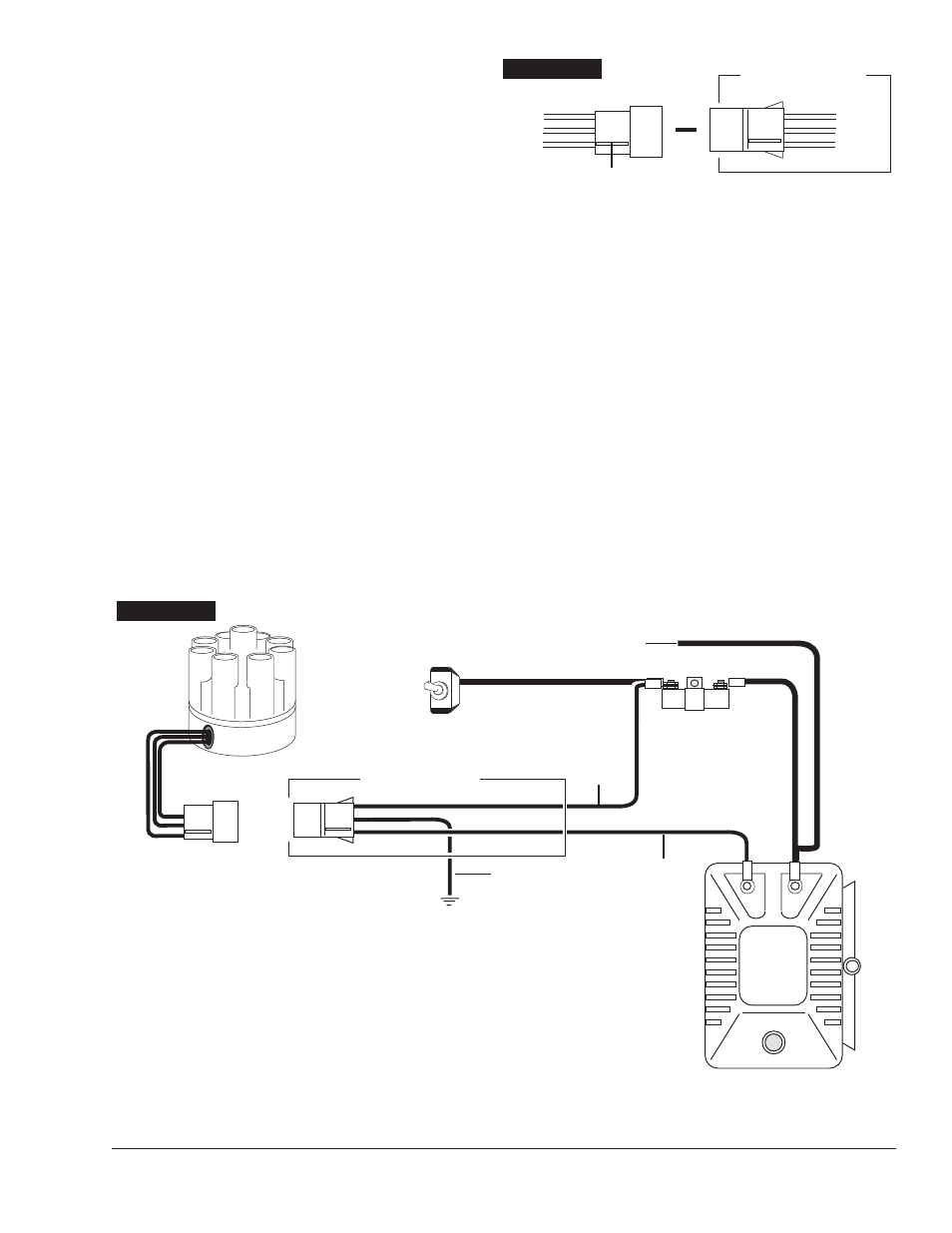
Step 12
Install the connector onto the wires. Be sure the wires
are in the correct positions (see Figure 15).
Step 13
Install the rotor shutter assembly. Make sure the
rotor/shutter does not rub on the module or wires.
Step 14
Reinstall the distributor using the rotor for a reference.
Reinstall the cap.
Step 15
Connect the wire harness to the connector. Connect
the 3 wires to the correct locations, as shown in
Figures 16 and 17.
Step 16
Set the ignition timing. Start the engine and
recheck timing.
FIGURE 15
Red
Brown
Green
Female Connector
Index Rib
Distributor Wire Harness
Red
Brown
Green
▼
+
COIL
–
FIGURE 16
12V/Ignition
Switch
Distributor Wire Harness
Part No. 29349
Ignition Ballast
Resistor
All other wires originally connected
to the coil (+) terminal
Ignition Module
Female Connector
Engine
Ground
Brown
Green
Red
NOTE: The purpose of an ignition ballast
resistor between the ignition switch (12V)
and the ignition coil positive terminal is to
restrict current flow through the ignition
coil. Failure to use an ignition ballast
resistor will eventually destroy the Ignition
Module.
EXCEPTION: If your vehicle is equipped
with a HYFIRE
®
Electronic Ignition Control
or similar aftermarket ignition control, use
the wiring procedures stated in the instructions
included with the ignition control.
To prevent false triggering and possible
premature ignition failure, you must use
suppression type (carbon core, spiral
core, or radio suppression core) spark
plug wire.
DO NOT USE SOLID CORE (COPPER
CORE OR STAINLESS STEEL CORE)
SPARK PLUG WIRE WITH ANY
ELECTRONIC IGNITION SYSTEM.
EQUIPPED WITH EXTERNAL BALLAST RESISTOR